Hello ,
I have a well preserved Sony PS-X65 but is defect.
So , motor don"t spin , light are on , 33 is present but don"t change speed , Locked is missing , no other function at all.
If I put a record on platter and move arm at the middle of the record , after pushing Power On button , the arm is moving back to suport.
What voltages I already checked and seems OK :
- from PS the + / - 31V are OK
- from IC101 the 5V and 11V are present and OK
- from IC 108 all voltages are according service manual (+ / -15V on pin 4 & 8 and 0V on others pins)
- from IC107 all voltages OK
- from MB8841-327 there is 5V on pin3
What voltages are not OK when Power is on:
- Q110 at B= 0,033V
- Q112 at B=0.2V
- Q111 at B=0.005V , C=3.56V , E=1.37V
Hope the MB8841-327 is Ok....
New electrolytics for main board are ordered for recap.
Can somebody explain me what is wrong here?
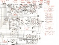
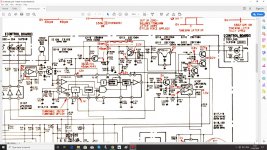
I attached mainboard and block diagram from service manual(schematic seems too big for upload but I will try somehow to shrink it).
Regards,
Bogdan
I have a well preserved Sony PS-X65 but is defect.
So , motor don"t spin , light are on , 33 is present but don"t change speed , Locked is missing , no other function at all.
If I put a record on platter and move arm at the middle of the record , after pushing Power On button , the arm is moving back to suport.
What voltages I already checked and seems OK :
- from PS the + / - 31V are OK
- from IC101 the 5V and 11V are present and OK
- from IC 108 all voltages are according service manual (+ / -15V on pin 4 & 8 and 0V on others pins)
- from IC107 all voltages OK
- from MB8841-327 there is 5V on pin3
What voltages are not OK when Power is on:
- Q110 at B= 0,033V
- Q112 at B=0.2V
- Q111 at B=0.005V , C=3.56V , E=1.37V
Hope the MB8841-327 is Ok....
New electrolytics for main board are ordered for recap.
Can somebody explain me what is wrong here?
I attached mainboard and block diagram from service manual(schematic seems too big for upload but I will try somehow to shrink it).
Regards,
Bogdan
Attachments
I would take a look around IC106 to ensure supply voltages are present firstly.
Next check for supply to pin 8 of IC108.
Then look at the waveform on pin 8 IC102
Rule of thumb for Sony products, the largest chip is rarely at fault.
Next check for supply to pin 8 of IC108.
Then look at the waveform on pin 8 IC102
Rule of thumb for Sony products, the largest chip is rarely at fault.
Hello,
Here are the measurement results on IC 106 :
pin2=2.36V
pin6=0V (!!!!!) --> should be 5.1V
pin7=2,7V
pin11=1.16V
pin21=0.026V (!!!!!) --> should be 2.2V
Measurement results on IC108 are:
pin1=-2.5V
pin4=-14.63V
pin8=14.67V
others pins voltages are 0V
I don"t have osciloscope unfortunately.
Thanks for help.
Bogdan
More measurements after checking why is missing 5V on pin6 from IC 106:
- Q114
B=0V (!!!!!) --> should be 2V
E=0V
-IC 107
pin5=0V (!!!!) --> should be 1.6V
pin6=0V (!!!!) --> should be 1.4V
pin7=0V (!!!!!) --> should be 1.5V
According block diagram Servo Amp is dead.
What components should I replace when recap?
Bogdan
- Q114
B=0V (!!!!!) --> should be 2V
E=0V
-IC 107
pin5=0V (!!!!) --> should be 1.6V
pin6=0V (!!!!) --> should be 1.4V
pin7=0V (!!!!!) --> should be 1.5V
According block diagram Servo Amp is dead.
What components should I replace when recap?
Bogdan
Here is a part of schematic , regarding NOK voltages from servo amp where voltages are wrong.
I can not upload full pdf file,exceeds the limit for upload.
On IC 107 I have + / - 15V on pin4 & pin8 but 0V on pins 5,6,7.
On IC 106 there is 5.64V on pin22 but 0V on pin 6 (should be 5.1V)
On Q114 there is B=0V.
Wrong voltages on Q110,Q111,Q112 (see post#1)
Bogdan
I can not upload full pdf file,exceeds the limit for upload.
On IC 107 I have + / - 15V on pin4 & pin8 but 0V on pins 5,6,7.
On IC 106 there is 5.64V on pin22 but 0V on pin 6 (should be 5.1V)
On Q114 there is B=0V.
Wrong voltages on Q110,Q111,Q112 (see post#1)
Bogdan
Attachments
What about IC106 pin 9 & 12? Should be +6V. Does pin 23 ground show continuity all the way to CNJ1, wherever hat goes off to? Do the solder joints all look good? Bigger DIPs with substantial power dissipation like cracking theirs.
It is unfortunate that you don't have a scope, which will make it hard to check whether the reference quartz oscillator is running. In this thread it actually turned out to be a duff crystal that caused a no-spin.
It's still odd not to be seeing anything at IC106 pin 21. If the pictogram is anywhere near accurate I would expect the 2.2 V out to be present at all times as long as +6V and ground are applied. Might be a dead chip - a fault noted for the PS-X45, for example. Not an easy one to find, unfortunately.
Hello,
Checked voltages on IC 106 and:
- pin9=5,64V
- pin12=5,64V
- there is continuity from pin23 to CNJ1 (checked with multimeter).
I am wonder , if there are 0V on pin6 (where should be 5.1V) -->this pin is feeding pin6 on IC 107.....Also at Q114 is B=0V.....means that Q114 is turned off.
I didn"t flip over the mainboard yet to see how it looks.
Bogdan
More measurements results:
On IC 106 (CX193) :
- pin2 = 2,36V
- pin5 = 0V
- pin6 = 0V
- pin7 = 2,7V
- pin9 = 5,64V
- pin12 = 5,64V
- pin21 = 0,026V (wrong ? )
- pin22 = 5,64V
On IC 107 (uPC4557C)
- pins 4&8 = +/- 14,64V
- pin5 = 0V (wrong?)
- pin6 = 0V (wrong?)
- pin7 = 0V (wrong?)
On IC 108 (uPC4557C)
- pin1 = - 2,5V
- pins 4&8 = +/- 14,64V
Q114 with B = 0V , E = 0V
Q110 with
- B = 0.032V (should be 0.2V)
- C = 0.19V (should be 0.7V)
Q112 with
- B = 0.19V (should be 0.7V)
- C = 0.86V (should be 0.2V)
- E = 0V
Q111 with
- B = 0.005V (should be 0.8V)
- C = 3.55V (should be 0.2V)
- E = 0.68V (should be 0.2V)
Attachement from the schematic below.
Is the CX193 dead or what?
regards,
Bogdan
It's still odd not to be seeing anything at IC106 pin 21. If the pictogram is anywhere near accurate I would expect the 2.2 V out to be present at all times as long as +6V and ground are applied. Might be a dead chip - a fault noted for the PS-X45, for example. Not an easy one to find, unfortunately.[/QUOTE]
Checking for voltages at pin21 of CX193 and trace back shows that pin21 is feeding from pin 34 of MB8841-327 where I have 4,9V.
I have also 4,9V at one end of R191.
At the other end of R191 there is 0.026V (same at pin21).
Maybe bad resistors R191 , R192 , R190.
I didn"t pull them out but measurements on mainboard shows that only one is 33K , 2 of them shows 17K.
Replaced R191 , R192 and R190 with new ones and still 0,026V at the other end of R191 and pin21 of CX193.
All were OK when measured off the mainboard.
I dont"t understand : if enter 5V on one end of R191 and R191 with R192 is a voltage divider (both 33K) , why not half voltage is present at their middle junction?
All were OK when measured off the mainboard.
I dont"t understand : if enter 5V on one end of R191 and R191 with R192 is a voltage divider (both 33K) , why not half voltage is present at their middle junction?
Attachments
Normally this should be dominated by the regulator inside the IC... which in turn may be shorted to ground.I dont"t understand : if enter 5V on one end of R191 and R191 with R192 is a voltage divider (both 33K) , why not half voltage is present at their middle junction?
Bummer, but not entirely unexpected at this point.Xtal X101 exchanged with a new one --> nothing , motor dont"t start.
Do you think you could isolate pin 21 - perhaps lift the ends on R190-192 (with some extra wire if needed) so they'll meet in mid-air instead? You might get lucky and the regulator is the only bit in the IC that's faulty. This should at least restore some level of operation, and if this regulator bit is needed it could be replicated externally (by changing the 33k/33k divider for something lower impedance R/RC perhaps, but I'm sure they'll have had their reasons for going this route in the first place).
Interesting approach , I will do that to check this.
Anyway , a new CX193 is ordered , before complete exchange I will try this idea.
When I push power button , I can see a small incremental platter rotation but backwards (like on the watch from 12.00 o"clock to 11.50 o"clock).
I didn"t mention this before.
If the motor is the problem , a new motor arrived from a PS-X70.
But changing the motor is the last thing I"ll do for this unit.
CX193 exchanged --> now the motor start to spin backwards.
Sometimes by himself but most of the times needs a little manual push.
It starts slowly but at the end reach full speed.No other function available.
Still wrong voltage on pin 21 of CX193 , still 0.026V.
I didn"t check other NOK voltages.
Regards,
Bogdan
Sometimes by himself but most of the times needs a little manual push.
It starts slowly but at the end reach full speed.No other function available.
Still wrong voltage on pin 21 of CX193 , still 0.026V.
I didn"t check other NOK voltages.
Regards,
Bogdan
Did the new chip look like new new or more like a pull? Not sure whether this is better or worse than with the old one.
There couldn't be any short to ground at pin 21, could there? I mean, I don't see where else it could be if not in the IC (I suspect shorted zener), but...
There couldn't be any short to ground at pin 21, could there? I mean, I don't see where else it could be if not in the IC (I suspect shorted zener), but...
Hi,
The new chip CX193 was new new --> no trace of previous mounting in another PCB
Resuming the symtoms of the turntable after more checkings:
1)The platter spins in any direction of manual push (could be backwards or normal spin).
2)When spinning normally , apparently reach speed of 33 RPM (not shure , it looks like).
3)When spinning backwards , apparently try to reach more speed (after a while).
4)Motor don"t spin by himself if rotating ax , only with platter assembled
5)A low noise coming out from motor when spinning (something like Wau-Wau-Wau , a sinusoidal noise , louder in one specific point and lower in rest).
6)Motor start to spin imediatly after pushing "Power ON" button --> no other button works
It seems that only one coil is working inside (just a though) --> motor has 2 coils according schematic and other posts from other users.
Full recap of the mainboard with Nichikon and Elna caps in progress --> small delay of this job due wrong ordering (bipolar caps instead of elytics caps).
Regards,
Bogdan
- Home
- Source & Line
- Analogue Source
- Sony PS-X65 turntable - motor don"t spin