Hello! I need help in figuring out a fault in a CD player.
I have recently acquired a CDP-X339ES that was sold as faulty.
The good part is that the laser diode works and manages to detect when a CD is inside and can (at least I think it can) properly focus the beam.
The bad part is that is has a fault that I have not been able to find, anywhere on the net: when I load a CD, the spindle wants to start, manages to spin the disc a bit, then stops and a click can be heard right then. After this the process is repeated.
Now, my guesses as to why that click can be heard are: 1. the laser head, while focusing, hits the CD disc, then quickly retracts, or 2. the platter of the spindle is not properly seated or detaches, loosing grip and not being able to make contact.
Can someone help me and tell me his/her opinion about what might be wrong with this player?
Here is a short video, showing the fault and the "click" in question.
https://www.youtube.com/watch?v=7RHqpwPbJ1Y
P.S. I apologize for my bad filming of this video.
Ok, so I tried putting in a CD and whilst the spindle was trying to spin it, I gave it a little push. At a certain speed, the clicking went away, but still the spindle motor did not start.
Could this be as simple as a dead spindle motor?
Could this be as simple as a dead spindle motor?
Nope, not the spindle motor. Took the whole thing apart, put some 3.5 Volts on the spindle motor and it turns, no problem. So it's back to the " lens hitting the disk" question.
It sounds as though it's the Lens hitting the Disc or the Lens ''Bottoming Out''.
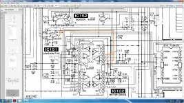
Possible Servo Drive IC fault? IC102
Still could be the Laser though. KSS-272? Hard to find now.
Service Manual Here.........
Sony CDP-X339ES Manual - Compact Disc Player - HiFi Engine
Possible Servo Drive IC fault? IC102
Still could be the Laser though. KSS-272? Hard to find now.
Service Manual Here.........
Sony CDP-X339ES Manual - Compact Disc Player - HiFi Engine
Well, I'm hoping it's something cheaper and easier to find 😀
From playing around with this unit, I've detected that there is a periodic loss of regulation on the -2V line (or the VEE line) which is used as d ground for the linear actuator driver and the servo driver.
These coincide with the "clicking" noise I hear. The behavior is that when the click can be heard, the -2V line rises to about +1V then enters regulation again.
My guess is that this is caused by the linear actuator motor, that moves the lens assembly back and forth. the reason I say this is that I can see some dips, although not as high amplitude, when I power on the CD player and the sleigh moves back and forth.
I have checked the capacitors on the -2V line and they seem OK (capacitance value and ESR value)
If it is indeed the linear actuator, the that means that when a CD is inserted, the click I hear is from the linear motor, hitting the end of the rail.
But why would it doing this...this is the question now
I read it that the VEE Line should be -0.2V The Manual seems to be a little contradictory to say the least!
Q951 with (+) 4V on its Collector! I think the scan has missed the negative sign off. But the Zener D964 with +5V on its Cathode would therefore have -2.5V on its Anode, if it is indeed a 7.5V Zener (the Manual though says there should be -0.8V !) therefore taking into consideration the 0.6V drop across the Transistor should as you say give -1.9V on its Emitter giving you your -2V VEE. However, everywhere it goes on the Manual it says -0.2V !
Can you do some readings so we know exactly what we're dealing with ?!?!
If it's going Positive though, there's something going wrong somewhere I would assume.
I'd start with Q951 and D964 and make sure your +5V is good from IC951.
@percival007: Indeed, I have also noticed discrepancies between the service manual test point voltages and actual circuit behavior. The VEE line, for example, is labeled on the PCB as "-2", so so much for trusting it.
So, I've done some more investigations, particularly around the suggested regulator, and indeed, something is going on, but without someone else measuring their own CDP-X339, to see how this rail actually behaves, I can not say for sure this is a fault. But anyway the results of my measurements are as follows: (every voltage value measured is referenced to GND)
- The +5V line is all fine and dandy, even when the linear actuators are moving.
- The voltage on diode D964 is 7.3 V, but this drops to about 6.5 V when the focusing coils and/or tracking coils are moving, NOT when the Linear actuator for the optic block is homing back and forth.
- The measured voltage on Q951's Collector with respect to GND is -2.36V, ad not 4V as the manual says. This makes sense, because that line sits at ABOUT -2V from GND. I don't know how they referenced that "4" they printed on the manual. Anyway, this voltage drops to -1.8 V when the Focusing/Tracking coils are moving
- The actual VEE line is -1.7V and this drops also, to -1.1V when the Focusing/Tracking coils are moving. This also makes sense, because if the voltage on the diode drops, it takes the whole regulated rail with it.
- I have also scoped the VEE rail and the voltage across C952 (see attached pic) and it has a ripple voltage of about 200mV. I have measured the capacitance of C952 and also the ESR (which is about 35 - 40 miliOhms) and it seems OK.
Now, the unregulated VEE, tapped off from the anode of D964 is feeding to the Linear motor that makes the optics move back and forth, while the regulated VEE (from the Emitter of Q951) goes to the coils for the focus and tracking.
Now, I doubt anyone is going to take the cover off their 339 and help me with some voltage measurements or oscilloscope pics to see how this rail behaves, but I doubt it should be taken out of regulation up to +1V.
So it's either a defective IC141, pulling down the whole rail, or a misbehaving regulator (D964, Q951)
I have measured also C955 and that seems to be OK (capacitance and ESR wise)

Well, it's not Q951 at fault. I've replaced that with a similar PNP and still the same behavior. Also, I've taken C956 off, which is connected to the base of Q951, and capacitance value is OK, also the ESR (about 0.8 Ohms, datasheet specifies this series as having 1.4 Ohms ESR)
All I have left is the Zener itself, after which, I will have to start suspecting either a faulty driver for the coils or indeed, as some have said, poor laser power. But this last one is a bit of a mongrel, because the adjustment pots are on the optic block, underneath the tray. So to do calibration on this thing, while a CD disk is in is impossible....at least without me knowing the proper calibration procedure.
All I have left is the Zener itself, after which, I will have to start suspecting either a faulty driver for the coils or indeed, as some have said, poor laser power. But this last one is a bit of a mongrel, because the adjustment pots are on the optic block, underneath the tray. So to do calibration on this thing, while a CD disk is in is impossible....at least without me knowing the proper calibration procedure.
You may be able to get to the pots on the Laser if you use a 3 inch CD Single, if you have one.
Or remove the Clamper Assembly and the Tray. Then using the Magnet from the Clamper Assy (it should just twist apart) you may be able to get to something(?).
It does look like it's going to be the Laser.
As the Laser Lens is moving too violently I suppose there's a very slim chance of the Feedback Resistors going O/C around the Driver IC but I doubt it. As you say, it's more likely to be the IC itself or even more likely, the Laser. 20+ years old so it's very likely to be on its way out.
Before having a crack at the laser itself, I still want to do a little more experimenting with other chips on the VEE rail, especially IC 152, which is in charge of some feedback from the coil. I'll try and swap that with IC 142. It's a log shot....but who knows. I'm too stubborn to leave this alone, just yet 😀
If all else fails, I have an 333 CD player, and I'm thinking of scavenging the laser assembly off of that and putting them into my 339, and see if that works. It's a lot of work, but better than having a go at some pots I barely see, let alone adjust.
I'll be posting progress reports as things move along. Hope I won't damage the thing even more.
Thank you for you help so far.
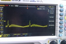
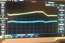
I managed to fit some lead wires on the optic unit itself, in order to see some signals that might be of interest. The first is the LDON signal (First picture) This looks like it's happily going about it's business, and it is ON when powering the CD player on, when inserting disk....it looks OK. Note that the LDON signal is the yellow trace, while the blue trace is the -2V line.
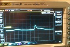
The second signal is Pin 25 on IC 102 (Second picture, yellow trace) and this looks like it's following the click that I hear, also visible in the -2V line (the blue trace) as rising peaks. The signal is the output from the comparator for the SRDR and SFDR signals.
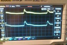
The third signal is Pin 11 on IC 102 (Fourth pic), basically what would be the signal from the feedback coil. Now this looks kind of promising....there's a nice ramp, and at some point, the signal falls abruptly (for about 70-80 ms), the comes back, and so on, this also coinciding with the rises in the VEE line. This signal comes straight from the Digital Servo, IC 101, so my guess is that this wouldn't have any reason to behave like that, would it ?
Also, I scoped the same line when the CD player is turned on (last picture) and it moves the lenses, to figure out if there already is any CD inside, and, with no disk inside, I see a nice ramp, so it's hard to believe that IC 102 is at fault here.....
Maybe some of the comparators, IC 151, IC 152 are causing this. Or maybe there's something actually going on to the digital servo controller (bad caps, resistors...) ?
I'm kind of stumped right now.
The second signal is Pin 25 on IC 102 (Second picture, yellow trace) and this looks like it's following the click that I hear, also visible in the -2V line (the blue trace) as rising peaks. The signal is the output from the comparator for the SRDR and SFDR signals.
The third signal is Pin 11 on IC 102 (Fourth pic), basically what would be the signal from the feedback coil. Now this looks kind of promising....there's a nice ramp, and at some point, the signal falls abruptly (for about 70-80 ms), the comes back, and so on, this also coinciding with the rises in the VEE line. This signal comes straight from the Digital Servo, IC 101, so my guess is that this wouldn't have any reason to behave like that, would it ?
Also, I scoped the same line when the CD player is turned on (last picture) and it moves the lenses, to figure out if there already is any CD inside, and, with no disk inside, I see a nice ramp, so it's hard to believe that IC 102 is at fault here.....
Maybe some of the comparators, IC 151, IC 152 are causing this. Or maybe there's something actually going on to the digital servo controller (bad caps, resistors...) ?
I'm kind of stumped right now.
Attachments

Hmm, I'm not convinced there is anything wrong here.
Apart from the VEE rising towards Zero but even this maybe just being caused by the Player struggling.
As I understand it..........
The Focus Servo will work at its hardest when first looking for a Disc.
The Coils are driven so that the Lens rises and falls as it looks for the best Focused Signal back from the Laser Receiving Diode. This corresponds to your Ramped Signal trace. It doesn't work this hard when playing so the Supplies for this circuit will have been made to cope with normal playback with just a little extra for this initial Focusing. So some 'drop' in the supplies may be normal.
If the Player gets a poor quality signal back from the laser, but does get something, then it will continue to look with the Feedback trying to (over(?)) compensate for the poor signal so the Lens hits the Disc surface, the clicking.
I would get that Laser from your donor player (it is the same isn't it?). 10 minute job to change and it would rule in or out whether it is in fact a failed Laser.
James.
Unfortunately, it's not that simple to change the optic block, because the 333 has a KSS-271A, and the 339 has a KSS-272A.
It needs the F+ and F- pins switched between then and also pin 11 on the chip that is on the optical block connected to pin 10. It may sound simple, but it is a hassle, so as much as possible, i would leave this as a last resort, although, indeed, what you are saying about the weak laser power sounds logical, and this is what I am afraid is happening.
It needs the F+ and F- pins switched between then and also pin 11 on the chip that is on the optical block connected to pin 10. It may sound simple, but it is a hassle, so as much as possible, i would leave this as a last resort, although, indeed, what you are saying about the weak laser power sounds logical, and this is what I am afraid is happening.
- Status
- Not open for further replies.
- Home
- Source & Line
- Digital Source
- Sony CDP-X339ES CD player Problems