Shouldn’t the motor be mounted „behind“ the spring, so that any vibration of it get absorbed too?
Shouldn’t the motor be mounted „behind“ the spring, so that any vibration of it get absorbed too?
Can't quite understand what you have in mind. 🙁
Can you draw up a sketch?
Hi, very interesting subject, I like 👍
For my TT I did heavy springs (heavy because plinth + platter + arm + bearing are over 16kg together) dumped with common sanitary silicone. Motor is not attached to the plinth.
I'm not turntable builder, but I am mechanical engineer as a matter of fact. Suspension is always mass + spring + velocity (of force causing oscillation) + dumping. Heavier mass = lower frequency, softer springs = lower frequency. If the mass is large, springs can be stiffer (and must be to support weight).
This doesn't work without dumping (imagine car driving only on springs, that would be quite bumpy) .
In our case (comparing with cars) velocity and forces causing oscillations are really minimal, so dumping does not need long travel.
Hydraulic dumping would be preferred, but very soft silicone comes close I think, without mess.
Here is picture:
I'm in process of rebuilding this TT and so far only touched upon vibration measurements, did some while playing test record.
Here I have seen this phone app "physics toolbox" and just as it is so easy I quickly used it. Did not find the way how to save measurements yet, but what I did is:
What would be extremely useful in such discussions, is to first establish correct and repeatable test method. That would allow for some progress, as without measurements, no management...
Cheers,
Drazen
For my TT I did heavy springs (heavy because plinth + platter + arm + bearing are over 16kg together) dumped with common sanitary silicone. Motor is not attached to the plinth.
I'm not turntable builder, but I am mechanical engineer as a matter of fact. Suspension is always mass + spring + velocity (of force causing oscillation) + dumping. Heavier mass = lower frequency, softer springs = lower frequency. If the mass is large, springs can be stiffer (and must be to support weight).
This doesn't work without dumping (imagine car driving only on springs, that would be quite bumpy) .
In our case (comparing with cars) velocity and forces causing oscillations are really minimal, so dumping does not need long travel.
Hydraulic dumping would be preferred, but very soft silicone comes close I think, without mess.
Here is picture:
I did not want the motor attached to the plinth, so i installed in new part, housing, and plinth resting on 4 heavy springs (heavy because the weight of this is significant) heavily dumped by common flexible sanitary silicone. Here are few pictures before housing was made, I used it like this for several months:


I'm in process of rebuilding this TT and so far only touched upon vibration measurements, did some while playing test record.
Here I have seen this phone app "physics toolbox" and just as it is so easy I quickly used it. Did not find the way how to save measurements yet, but what I did is:
- place the phone on plinth and started g-meter
- gave one strong knock on the plinth, like knocking doors
- used just g-meter, and than repeated with FFT analysis
- resonant frequency under or about 3Hz
- all gets quiet in about 2 s
What would be extremely useful in such discussions, is to first establish correct and repeatable test method. That would allow for some progress, as without measurements, no management...
Cheers,
Drazen
A few points. The best vibration isolation is obtained when resonant frequency of spring system is 3 Hz or below, preferably below 2 Hz. Since the spring system acts as mechanical low pass filter the Fr must be very low to provide sufficient isolation at 10Hz. There would be precious little isolation at 10 Hz if spring system Fr was 6 Hz, for example. There is also the issue that seismic type vibration (e.g., traffic, footfall, earth crust motion) occurs in 6 directions of motion. Most spring systems only isolate in one direction, the vertical. Also, I’m not a fan of damping the springs. The springs should be free to move easily without constraint. Ditto for the turntable. The easier it can move the better the isolation.
Last edited:
Hi, this is just partially correct.Most spring systems only isolate in one direction, the vertical.
Spring does have better defined characteristic in on axis direction (vertical in our case) but it also has characteristics in horizontal direction (left-right. back-forward).
Correct is that horizontal characteristic is different from on axis (vertical) and should be observed.
Amorphous damping, like silicon, will behave similar in all directions do. If spring is log enough and dumped, "seismic" kind of vibrations (that wave building left and right) should be under control... Now this what I said I never calculated neither measured, so take it with reservations.
So this design wouldn't cushion in all 6 directions?There is also the issue that seismic type vibration (e.g., traffic, footfall, earth crust motion) occurs in 6 directions of motion.
Consider a pendulum design.
Lateral isolation to a couple of Hz. Vertical isolation if the suspension is compliant. Just tension the vertical elements slightly with elastic.
Very effective filtering.
Lateral isolation to a couple of Hz. Vertical isolation if the suspension is compliant. Just tension the vertical elements slightly with elastic.
Very effective filtering.
SME also did it many years, decades, ago...

Even it suspends in all directions, characteristics is still different from vertical to horizontal dimensions.
In addition o-rings are less predictable and age, compared to springs. Nevertheless the do have nice feature of being spring and dumping in one....
But than again, who listens to TT during quake 😁.
Worst problem I experienced is 20 people dancing on parquet floor supported by wooden beams in old house.... That's mostly vertical movement
The same logic applies to CD Players and transports, the tiny springs the laser assembly is attached to have a relatively high resonant frequency so the laser is easily moved back on track if necessary, which is frequently btw. lol. So, seismic type vibrations get through. The ones between 0 and 15-20 Hz, which is where most seismic type energy lies 0-20 Hz. That’s why properly isolating a CD Player/Transport is important, isolating with sub 3 Hz iso system . For the horizontal plane there is an infinite number of directions, no? I need convincing that horizontal forces are good for rotating heavy mass TT platters.
Last edited:
I probably misspelled, here’s the official thing:Can you draw up a sketch?
Attachments
Isolation above resonance frequency of spring/mass is inverse of damping applied. I believe you can see X/Y & Z axis resonance in the measurements I took and posted earlier. This shows that the springs isolate in more than one direction.
Drazen, you could use the physics toolbox app I posted earlier to measure. It is a bit of a pain to take the data output filter and plot the graphs but workable and free if you have access to excel or some similar spreadsheet program.
Drazen, you could use the physics toolbox app I posted earlier to measure. It is a bit of a pain to take the data output filter and plot the graphs but workable and free if you have access to excel or some similar spreadsheet program.
Hi Martyh, I just installed it today, looks good. When time allows I'll check how to record and save files.
Also happy that my TT shows quite nice measure at first go, never tested like this.
Still would be good to establish some simple measurement procedure so results can be comparable...
Also happy that my TT shows quite nice measure at first go, never tested like this.
Still would be good to establish some simple measurement procedure so results can be comparable...
^
I have seen some measuring self damping of plinth material drop a specified weight from a certain distance and measure to compare but I don't think that will work in this case. As far as determining the resonant frequency of the spring mass I think any excitation will work as the system settles in to the frequency relatively quickly. The proper amount of damping is another thing though. Maximum suppression at arm/cart and audio frequencies calls for low as possible frequency of spring/mass and no damping, but then letting the whole system resonate so long just feels wrong. I guess that a slow enough cycle to keep grove /stylus pressure constant or nearly so would work but I have no idea how one would go about calculating that.
I have seen some measuring self damping of plinth material drop a specified weight from a certain distance and measure to compare but I don't think that will work in this case. As far as determining the resonant frequency of the spring mass I think any excitation will work as the system settles in to the frequency relatively quickly. The proper amount of damping is another thing though. Maximum suppression at arm/cart and audio frequencies calls for low as possible frequency of spring/mass and no damping, but then letting the whole system resonate so long just feels wrong. I guess that a slow enough cycle to keep grove /stylus pressure constant or nearly so would work but I have no idea how one would go about calculating that.
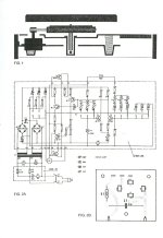
I probably misspelled, here’s the official thing:
That looks weird ... but interesting! 🙂
If the motor really is resting on its own subchassis - which is different to the one supporting the bearing and arm wand - then I would think it should work quite well.
I think that is a cutaway drawing of a Thorens table, a pretty common layout, Linn, AR, etc.
It may well be a dwg of a Thorens ... but a Linn has its motor fixed to the top-plate. (And the bearing and armboard fixed to a subchassis which is connected to the top-plate by springs & bolts.)
^
Right, same as AR. the point is the motor is mounted on the other side of springs that support the platter bearing and arm. Linn springs actually work well in the td125 because they are doing the same thing in both cases.
Right, same as AR. the point is the motor is mounted on the other side of springs that support the platter bearing and arm. Linn springs actually work well in the td125 because they are doing the same thing in both cases.
It’s the „schematic“ of a td-125 🙂 and yes, the motor is on it’s own stell-plate (with electronics and switches), while the platter and armboard are suspended on 3 slightly damped springs…
It depends, it depends on how far apart the springs are arranged. You can get some rotational isolation if the springs are closer together, generally speaking. Most steel springs are very stiff in the lateral plane, which means they do not provide much isolation at all in the lateral plane. One solution generally speaking is to incorporate bearing plates with springs, one on top of the other, but maybe not for turntables, due to the issue of rotational forces. For turntables rotational forces can be somewhat dearth with but making the plinth and platter very stiff.Isolation above resonance frequency of spring/mass is inverse of damping applied. I believe you can see X/Y & Z axis resonance in the measurements I took and posted earlier. This shows that the springs isolate in more than one direction.
Drazen, you could use the physics toolbox app I posted earlier to measure. It is a bit of a pain to take the data output filter and plot the graphs but workable and free if you have access to excel or some similar spreadsheet program.
- Home
- Source & Line
- Analogue Source
- Some turntable suspension measurements