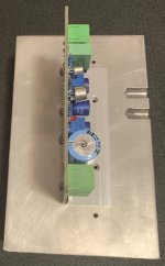
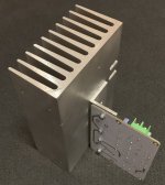
I got some ready-made JLH1969 modules, which came with a piece of aluminium L profile to be mounted to a heatsink. I found some heatsinks, that should be large enough and there are some threaded holes already. These would be perfect to fix the board exactly in the middle of the heatsink (2 holes fit). The heatsink will be placed upright, so I wonder if there was any benefit to placing the board as close to the bottom as possible - I would have to drill and tap one extra hole (see the pictures)
And my second question would be to the mounting of the L profile to the heatsink - if I am correct, I should sand and polish the matching surfaces and then apply just a little amount of heat conducting paste between them. Or should I skip the heat conducting paste if the surfaces are perfectly treated? Do I need a metal bar to press the L profile better or would just large washers do fine?
And my second question would be to the mounting of the L profile to the heatsink - if I am correct, I should sand and polish the matching surfaces and then apply just a little amount of heat conducting paste between them. Or should I skip the heat conducting paste if the surfaces are perfectly treated? Do I need a metal bar to press the L profile better or would just large washers do fine?
Attachments
The heat radiation is mainly from verical surfaces where convection currents occurs. So always try maximizing vertical surfaces.
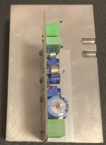
So the position of the L profile is not that important? The heatsink will be mounted into the enclosure in the standing orientation as in the second picture (there will be two, each board will have its own).
The second pic is the best of all postions. But it is a bit ugly to have the board vertical. So you can place the pcb horizontal mantaining the wings of the hs vertical.
Thanks. So horizontal as close to the bottom as possible? The vertical placement would allow best access to the terminals and trimmers from the sides.
And how about the heat paste? A little or none?
And how about the heat paste? A little or none?
Heat conduction between the L-bracket and the heat sink is by conduction. Placement centrally on the heat sink, as in your first photo, would give the shortest diffusive path to all parts of the heat sink (i.e., makes the best use of the entire heat sink). But the exact position isn't too critical to getting adequate heat transfer as the Al of the heat sink is pretty good at internally spreading heat. Given this, I also don't disagree with Osvaldo's suggestion to place the PCB horizontally if you wish to do that for aesthetic or other reasons, but see no reason to place it at the bottom. A more central position would be better.
No surfaces are perfect, even if they shine like a mirror to your naked eye. For example, a scanning electron microscope image would show asperities and valleys. So it is best to rub in a little heat paste, as it will improve the thermal conductivity by filling the micro-voids. You don't need much as long as the mating surfaces are flat; what looks like a thin haze on the surfaces should do it.
No surfaces are perfect, even if they shine like a mirror to your naked eye. For example, a scanning electron microscope image would show asperities and valleys. So it is best to rub in a little heat paste, as it will improve the thermal conductivity by filling the micro-voids. You don't need much as long as the mating surfaces are flat; what looks like a thin haze on the surfaces should do it.

Agree. Air is one of the best insulators there is. Even if the surfaces appear to be smooth, a thermal interface material can help the heat transfer dramatically. Your L-bracket appears to be fairly thin and could use all the help you can give it. Where I worked, the thermal analysts ignored heat transfer beyond 2-3 mounting screw radii if there was no thermal interface material. Increasing the number of screws, if possible, is also a good idea.No surfaces are perfect, even if they shine like a mirror to your naked eye. For example, a scanning electron microscope image would show asperities and valleys. So it is best to rub in a little heat paste, as it will improve the thermal conductivity by filling the micro-voids. You don't need much as long as the mating surfaces are flat; what looks like a thin haze on the surfaces should do it.
Agree. Also think in the possibility of get a hs that has the opposit disposition of flanges, and to put the transistors directly to it, avoiding the L shaped piece.
FWIW, this is the electronic microscope picture of a mirror bright metallic polished surface 😱 :

Straight from respected scientific researchgate.net huh?
Straight from respected scientific researchgate.net huh?
Thanks for all the replies. I am stuck with what I have, so I will polish the surfaces, add one more hole in the middle of the L profile and use a thin layer of heat paste.
If you want to do things "a little" well, apply a little of this paste evenly on the part in contact with the L and a little on the heatsink and literally rub the heatsink with the L, this will allow you to "conform" (I do not know the technical term in English) the two parties in contact.
It's overkill but it's an effective and simple solution.
https://www.amazon.fr/Ventileinschl...wicXNhIjoiMy43MSIsInFzcCI6IjMuMzYifQ==&sr=8-4
It's overkill but it's an effective and simple solution.
https://www.amazon.fr/Ventileinschl...wicXNhIjoiMy43MSIsInFzcCI6IjMuMzYifQ==&sr=8-4
Now I'm somehwat surpriesd, as I always thought the optimum placement is at the heatsink's coolest location, i. e. as close as possible to the bottom. And I'd also rotate the board by 90° ccw so that it comes horizontally.Placement centrally on the heat sink, as in your first photo, would give the shortest diffusive path to all parts of the heat sink (i.e., makes the best use of the entire heat sink).
Best regards!
Kay,Now I'm somehwat surpriesd, as I always thought the optimum placement is at the heatsink's coolest location, i. e. as close as possible to the bottom. And I'd also rotate the board by 90° ccw so that it comes horizontally.
Best regards!
I am not a thermal analyst [there must be some on this site] but I suspect that the optimal placement is closer to the center than the bottom end. This is because the heat source is not evenly distributed across the heat sink. All of the energy must come through the L-bracket, so wherever you attach it becomes the hottest part of the heatsink. The horizontal vs. vertical question depends on the placement of the power devices on the L-bracket. Vertical orientation may be superior for the same reason given by northpaw but I doubt that it makes much difference and other factors could make the determination.
Best regards,
Bruce
Kay - Interesting point.
I just measured the heat sinks on my Nakamichi PA-5 that has been running for an hour, and the air below and above the fins.
The heat sinks have a bottom T of 31.4°C, and a top T of 31.9°C. The air is 22.3°C below the fins, and 28.1°C above the fins.
The rather small temp gradient within the heat sink itself indicates it is fairly effective at distributing the heat generated by the output transistors (located about a third up the bottom of the heat sink in this design). The ~6° difference bottom to top in air temp indicates heat transfer from heat sink to moving air will somewhat better at the bottom (delta T of ~9°) than at the top (delta T of 3.8°). This presumably results in more dissipation occurring at the bottom than at the top.
So I think you make a fair point, but it is more due to differences in air temp than in heat sink temp. So I agree with Bruce above (who's post appeared as I was typing this) that the different choices in placement are not too critical in determining effectiveness (because heat transport within the heat sink is relatively rapid), and that factors such as ease or convenience of mounting might be more important for a particular builder.
Interesting debate, but on the other hand we are talking about a JLH69 which certainly is in class A, but given the supply voltage and the bias current, it does not need crazy heatsinks, just well arranged and with a little mass (weight).
Of the good ten that I have assembled, none has ever exceeded 50°C on the heatsinks, directly or with an L.
Of the good ten that I have assembled, none has ever exceeded 50°C on the heatsinks, directly or with an L.
If heatsink body is thick, there is virtually no top or bottom. low thermal resistance equalizes temperatures at different places.Now I'm somehwat surpriesd, as I always thought the optimum placement is at the heatsink's coolest location, i. e. as close as possible to the bottom. And I'd also rotate the board by 90° ccw so that it comes horizontally.
Best regards!
Imagine 2 main caps at a power supply, with pads joined not only by a track but by a rectangular area, say 2 cm by 3 cm.
No need to solder a ground wire to one or the other capacitor leg, practically all of that rectangle is at same voltage.
Same thing.
The best position for a device to be cooled would be a bit above the first third of the sink (for example, 4-5 cm above lower edge on a 12 cm high sink.
Because temperature is radiating in all direction, but air convection rakes in more energy (warmth seems to go upwards but that’s the air).
Furthermore, if there was a way to mount the devices directly to the HS, you would have one temperature-junction less (a junction works like a resistor)
Look at this excellent resource for a much better explanation: https://neurochrome.com/pages/thermal-design
northpaw,The heat sinks have a bottom T of 31.4°C, and a top T of 31.9°C. The air is 22.3°C below the fins, and 28.1°C above the fins.
Your PA-5 has impressive heat sink temperature uniformity! They must have given the thermal design some thought. I agree with your discussion of the temperature deltas. Well stated. Assuming that you have laminar air flow up the heat sink fins and they are warmer than the air, the air will be warmer at the top than at the bottom as it continues to pick up heat as it flows upward along the fins.
This is somewhat off-topic, but I, all too often, see amplifiers with a row of power transistors across both the top and the bottom of the heatsink. I'm sure that is done for convenience of the electrical layout, but it can't be optimum from a thermal standpoint.
Best reagards,
Bruce
Thanks! This was posted as I was composing my last message.The best position for a device to be cooled would be a bit above the first third of the sink (for example, 4-5 cm above lower edge on a 12 cm high sink.
Because temperature is radiating in all direction, but air convection rakes in more energy (warmth seems to go upwards but that’s the air).
Furthermore, if there was a way to mount the devices directly to the HS, you would have one temperature-junction less (a junction works like a resistor)
Look at this excellent resource for a much better explanation: https://neurochrome.com/pages/thermal-design
So I guess the Nak engineers knew what they were doing.The best position for a device to be cooled would be a bit above the first third of the sink
Thanks for the info and the link.
- Home
- Amplifiers
- Solid State
- Some quick heatsink mounting questions