Member
Joined 2009
Paid Member
Sounds very interesting !
Actually, I think I am one of the people who only have copied ideas from other people. I am sorry, but that is my limitation!
But if you have really good idea, ask yourself if you should keep it for yourself, perhaps to sell it.
Do not be sorry for this: the "blameless" is born once!
I have seen that in the time you have also tried new ideas and sooner or later it will come the most important one.
I think I'm lucky to have some good ideas such as:
- the single stage push-pull amplifier
- the circlotron stage with voltage gain
- the rediscovery of Vfet in se and pp amps
- the use of transformers as voltage gain element
- the new phase splitter (fully differential phase inverter).
Looking forward to seeing some new ideas!
Cheers,
Valery
OK. We begin the countdown !
Your design is very good, and i think it sound well as for Bigun schematic.
In your photo i see two 0,22 Ohm and four 0,1 Ohm 10 watt resistors, but these last I am not able to see in schematic.
Thanks, Francesco
OK. We begin the countdown !
Your design is very good, and i think it sound well as for Bigun schematic.
In your photo i see two 0,22 Ohm and four 0,1 Ohm 10 watt resistors, but these last I am not able to see in schematic.
Thanks, Francesco
Hi Francesco, here is an updated schematic. In fact, for 30W @ 8 Ohm load, one pair of output transistors is more than enough. However, if we want a 4 Ohm load and up to 50W in class A... that's why I have placed the second pair there.
Not all compensation caps will be used probably. Real world prototype's behavior is different from simulations in most cases, so we'll see 😉
Cheers,
Valery
Attachments
Member
Joined 2009
Paid Member
I like the IPS there, I had simulated a single LTP version in TGM4 but never built it. It's a kind of Lender/folded cascade thing that I thought just 'looked right'.
As promised, i have started a new thread on this section:
http://www.diyaudio.com/forums/solid-state/257200-two-new-output-stages-have-you-seen-before.html
Regards
http://www.diyaudio.com/forums/solid-state/257200-two-new-output-stages-have-you-seen-before.html
Regards
Be happy.... because audio quality matters.
regards,
Carlos
I will try all of my best, hoping that one day I can offer a good design for you. 😉
Thanks much, Francesco
For sure you gonna do it my dear friend Mos57
Fratello de la squadra azzurra!...brother from the blue Italian team.
I will look forward for you design and from other folks, the Russian is a clever guy too..and there are others too...i will come to see your stuff.
поздравления смелый русский товарищ..... greetings brave Russian comrade
Bigun is awesome...and there are much more to come.
Your home folks....welcome!....take a good chair in front of your computer and show us your ideas!
I am watching this stuff... i did it that way in 1960 when i started.... transistors where germanium..... it is nice to see this again..... i have used nails, breadboard and telephone multi wire cable:
https://www.youtube.com/watch?v=HrG98HJ3Z6w
regards,
Carlos
Quick update
Guys, here is a quick update on the development process )
I was a bit more busy the last couple of weeks than expected, however I have finished putting everything together and ran a few initial tests.
I have to admit, I made a stupid mistake while soldering the boards - VAS transistors (2N5401 / 2N5551) appeared exchanged (PNP <-> NPN), causing the signal not going through and neither NFB nor DC servo working at all, with OPS quiescent current somewhere at around 20A 😱
Such behavior made me think something is terribly wrong, I did some measurements, saw the voltage at +/-15V zeners is much lower than it should be (it was +/-3.5V), understood that something dramatically drains current from them and realized the VAS transistors were exchanged.
After putting the transistors to their correct locations, the whole thing started working!
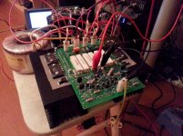
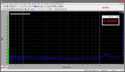
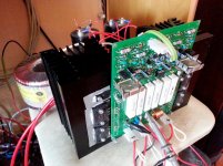
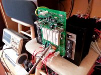
I have adjusted the OPS quiescent current to a pretty low one for the time being (400mA, to be on a safe side), added couple of caps to improve stability and ran some initial tests. See the pictures.
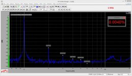
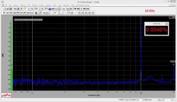
Output signal is 3.2V RMS at 20 Ohm load (deliberately using easy load at the moment). It is not even class "A" yet - it is a high-current "AB", however I really like harmonics distribution (2-nd one is strongly dominant) and the way THD increases with frequency increase (very lightly, no change observed up to 10 KHz and very slight increase at 20 KHz).
I will be away from home till Sunday - participating a skydive competition 450km away from Moscow, after that I will bring the amp to full throttle.
Stay tuned! 😉
Cheers,
Valery
Guys, here is a quick update on the development process )
I was a bit more busy the last couple of weeks than expected, however I have finished putting everything together and ran a few initial tests.
I have to admit, I made a stupid mistake while soldering the boards - VAS transistors (2N5401 / 2N5551) appeared exchanged (PNP <-> NPN), causing the signal not going through and neither NFB nor DC servo working at all, with OPS quiescent current somewhere at around 20A 😱
Such behavior made me think something is terribly wrong, I did some measurements, saw the voltage at +/-15V zeners is much lower than it should be (it was +/-3.5V), understood that something dramatically drains current from them and realized the VAS transistors were exchanged.
After putting the transistors to their correct locations, the whole thing started working!
I have adjusted the OPS quiescent current to a pretty low one for the time being (400mA, to be on a safe side), added couple of caps to improve stability and ran some initial tests. See the pictures.
Output signal is 3.2V RMS at 20 Ohm load (deliberately using easy load at the moment). It is not even class "A" yet - it is a high-current "AB", however I really like harmonics distribution (2-nd one is strongly dominant) and the way THD increases with frequency increase (very lightly, no change observed up to 10 KHz and very slight increase at 20 KHz).
I will be away from home till Sunday - participating a skydive competition 450km away from Moscow, after that I will bring the amp to full throttle.
Stay tuned! 😉
Cheers,
Valery
Attachments
Up and running
OK. Here it is.
I tried it with OPS quiescent current at 1.7A. Works great, quiescent current is very stable, however with my heatsinks it gets too hot - I can't touch them any more 🙂
So I have set 1A now. The temperature is somewhat around 90 degrees Celsius, rock-stable. Performance is slightly increased comparing to the previous measurements - excellent even at 10V RMS, 8 Ohm load. It's easily possible to go above 2A of quiescent current - just need bigger heatsinks. As always - class "A" amp is a high-performance heating system 🙂))
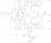
The very final version of the schematic is attached.
I will publish more graphs and measurements - just need to organize them for convenience. In a nut shell:
- THD is less than 0.003% @ 1KHz, less than 0.009% @ 20KHz - mostly 2-nd harmonic, 3-rd one is roughly 10 times less;
- IMD is less than 0.005%, measured with 14KHz and 15KHz waves at the same time. It is interesting, that the highest harmonics are F1-(F1-F2) and F2+(F1-F2) - 13KHz and 16KHz. The pure differential harmonic itself (1KHz) is negligible (0.0005%);
- Pure class "A" up to around 20W @ 8 Ohm (with 1A OPS idle current), then it seamlessly continues in class "AB" up to around 75W (almost touching the rails), then it clips cleanly and nicely - no sign of saturation (or "rail sticking") whatsoever.
- Square wave response - clean, with slight overshoot (I don't want to fight it though to preserve the other qualities), 800nS rise/fall time at full amplitude (more than 80V/uS slew rate).
As usual, I auditioned it with two Monitor Audio RS-8 speakers, connected serially to the output (6+6 Ohm).
Sound is very, very good - solid, very high-resolution, providing clear separation of sources even with one channel. It somehow gives an impression of a top quality valve amplifier. Extremely comfortable for listening during a long time. Advantages are most noticeable with high-resolution sources - SACD, 24/96 - 24/192 lossless digital formats.
It is highly repeatable - absolutely self-balancing design, no adjustments required if no mistakes are made and elements tolerance is reasonable (I used 1% for most of the resistors and matched in pairs all the transistors except the input FETs, drivers and OP big ones). Sanken rules again ))
If you want to change the OP idle current - just change R11 and R12 (the less the R value -> the higher the current). 2.7M will give you around 1.4A, 2.2M - 1.7A (this is what I practically measured, if you want higher currents - decrease the R value, but don't forget to use the bigger heatsinks).
For those who'd like to build it I provide full technical support 😉
Just be prepared to feel some heat 😀
Carlos - thanks again for inspiration!
Cheers,
Valery
OK. Here it is.
I tried it with OPS quiescent current at 1.7A. Works great, quiescent current is very stable, however with my heatsinks it gets too hot - I can't touch them any more 🙂
So I have set 1A now. The temperature is somewhat around 90 degrees Celsius, rock-stable. Performance is slightly increased comparing to the previous measurements - excellent even at 10V RMS, 8 Ohm load. It's easily possible to go above 2A of quiescent current - just need bigger heatsinks. As always - class "A" amp is a high-performance heating system 🙂))
The very final version of the schematic is attached.
I will publish more graphs and measurements - just need to organize them for convenience. In a nut shell:
- THD is less than 0.003% @ 1KHz, less than 0.009% @ 20KHz - mostly 2-nd harmonic, 3-rd one is roughly 10 times less;
- IMD is less than 0.005%, measured with 14KHz and 15KHz waves at the same time. It is interesting, that the highest harmonics are F1-(F1-F2) and F2+(F1-F2) - 13KHz and 16KHz. The pure differential harmonic itself (1KHz) is negligible (0.0005%);
- Pure class "A" up to around 20W @ 8 Ohm (with 1A OPS idle current), then it seamlessly continues in class "AB" up to around 75W (almost touching the rails), then it clips cleanly and nicely - no sign of saturation (or "rail sticking") whatsoever.
- Square wave response - clean, with slight overshoot (I don't want to fight it though to preserve the other qualities), 800nS rise/fall time at full amplitude (more than 80V/uS slew rate).
As usual, I auditioned it with two Monitor Audio RS-8 speakers, connected serially to the output (6+6 Ohm).
Sound is very, very good - solid, very high-resolution, providing clear separation of sources even with one channel. It somehow gives an impression of a top quality valve amplifier. Extremely comfortable for listening during a long time. Advantages are most noticeable with high-resolution sources - SACD, 24/96 - 24/192 lossless digital formats.
It is highly repeatable - absolutely self-balancing design, no adjustments required if no mistakes are made and elements tolerance is reasonable (I used 1% for most of the resistors and matched in pairs all the transistors except the input FETs, drivers and OP big ones). Sanken rules again ))
If you want to change the OP idle current - just change R11 and R12 (the less the R value -> the higher the current). 2.7M will give you around 1.4A, 2.2M - 1.7A (this is what I practically measured, if you want higher currents - decrease the R value, but don't forget to use the bigger heatsinks).
For those who'd like to build it I provide full technical support 😉
Just be prepared to feel some heat 😀
Carlos - thanks again for inspiration!
Cheers,
Valery
Attachments

OK. Here it is.
I tried it with OPS quiescent current at 1.7A. Works great, quiescent current is very stable, however with my heatsinks it gets too hot - I can't touch them any more 🙂
So I have set 1A now. The temperature is somewhat around 90 degrees Celsius, rock-stable. Performance is slightly increased comparing to the previous measurements - excellent even at 10V RMS, 8 Ohm load. It's easily possible to go above 2A of quiescent current - just need bigger heatsinks. As always - class "A" amp is a high-performance heating system 🙂))
The very final version of the schematic is attached.
I will publish more graphs and measurements - just need to organize them for convenience. In a nut shell:
- THD is less than 0.003% @ 1KHz, less than 0.009% @ 20KHz - mostly 2-nd harmonic, 3-rd one is roughly 10 times less;
- IMD is less than 0.005%, measured with 14KHz and 15KHz waves at the same time. It is interesting, that the highest harmonics are F1-(F1-F2) and F2+(F1-F2) - 13KHz and 16KHz. The pure differential harmonic itself (1KHz) is negligible (0.0005%);
- Pure class "A" up to around 20W @ 8 Ohm (with 1A OPS idle current), then it seamlessly continues in class "AB" up to around 75W (almost touching the rails), then it clips cleanly and nicely - no sign of saturation (or "rail sticking") whatsoever.
- Square wave response - clean, with slight overshoot (I don't want to fight it though to preserve the other qualities), 800nS rise/fall time at full amplitude (more than 80V/uS slew rate).
As usual, I auditioned it with two Monitor Audio RS-8 speakers, connected serially to the output (6+6 Ohm).
Sound is very, very good - solid, very high-resolution, providing clear separation of sources even with one channel. It somehow gives an impression of a top quality valve amplifier. Extremely comfortable for listening during a long time. Advantages are most noticeable with high-resolution sources - SACD, 24/96 - 24/192 lossless digital formats.
It is highly repeatable - absolutely self-balancing design, no adjustments required if no mistakes are made and elements tolerance is reasonable (I used 1% for most of the resistors and matched in pairs all the transistors except the input FETs, drivers and OP big ones). Sanken rules again ))
If you want to change the OP idle current - just change R11 and R12 (the less the R value -> the higher the current). 2.7M will give you around 1.4A, 2.2M - 1.7A (this is what I practically measured, if you want higher currents - decrease the R value, but don't forget to use the bigger heatsinks).
For those who'd like to build it I provide full technical support 😉
Just be prepared to feel some heat 😀
Carlos - thanks again for inspiration!
Cheers,
Valery
Congratulation Valery, as always very good design, not so simple, but then I myself usually could not keep KISS principle.
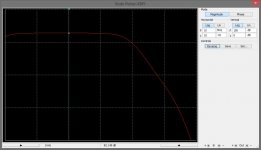
Could you show the Loop Gain?
Damir
Congratulation Valery, as always very good design, not so simple, but then I myself usually could not keep KISS principle.
Could you show the Loop Gain?
Damir
Thank you Damir 🙂
I can show the gain with open (1) and closed (2) GNFB loop - see attached.
So, the loop gain is roughly 82db - 28db = 54db, at least within the audio frequency range...
Attachments

Member
Joined 2009
Paid Member
Nice work indeed - it shows that high OLG is not an obstacle to good sound as some would have us believe (when the amplifier is designed right).
PCB
Here is a PCB in PDF format. Relatively easy to produce. No vias.
Size is 170x120mm.
BOM is also attached.
Cheers,
Valery
Here is a PCB in PDF format. Relatively easy to produce. No vias.
Size is 170x120mm.
BOM is also attached.
Cheers,
Valery
Attachments
 nilcely done vzaichenko!
Thank you Rawbas.
BTW - ran it for 2 days non-stop. Very stable in terms of temperature and key parameters. Really like the sound
Also, I monitored the output with oscilloscope all this time (just in case) and realized that in the apartment conditions it's really difficult to go out of "class A" region of operation, even with 1A quiescent current... 🙄
- Status
- Not open for further replies.
- Home
- Amplifiers
- Solid State
- Some people loves a challenge ....