Wahab,
what is happening at ~1.5MHz?
Is it worth trying to reduce that peak.
Could we hear that peak?
what is happening at ~1.5MHz?
Is it worth trying to reduce that peak.
Could we hear that peak?
vBulletin Message
Invalid Attachment specified. If you followed a valid link, please notify the administrator
Uncle,
I can't get past this message.
Wahab,
what is happening at ~1.5MHz?
Is it worth trying to reduce that peak.
Could we hear that peak?
The output impedance climb to almost 10R at this frequency.
Of course this peak in output impedance has no audibility
since it s at very high frequency.
What matters is the output Z in the audio band.
Increasing the open loop gain will yield lower closed loop gain output Z,
but i suppose that everybody know that.
Attachments
I can't see much theoretical discussion in this thread. One guy is trying to teach some theory. The other guy is covering his ears.sumaudioguy said:I am also very tired of this theoretical discussion.
There is probably something wrong with your measurement setup. If you measure the same thing in two different ways and get different results then at least one of them is wrong. The fact that you get particular problems around the line frequency is a bit of a giveway for external interference getting into your tests. An amplifier with a serious fault in its output protection circuit might measure differently, and an amplifier with a non-linear output impedance would need to be measured at the same test current for each, but apart from that you should get the same results because you are measuring the same thing!As a laboratory fact I have personally measured hundreds of power amplifiers on calibrated equipment and have yet to find one example which shows output impedance to be very similar to input impedance at the output terminals. These two are always frequency dependent and have not been found to be anywhere near equal except at the very lowest frequencies, less than 100Hz and never at the power line frequency. Input impedance at the output terminals has been found to be a complex circuit with several vary apparent resonances whereas the resistive portion of the output impedance usually follows a very smooth common first or second order filter.
As he is offering standard EE, the onus of proof is on you not him.All I ask is for jcx to (snip) demonstrate how correct his thinking is.
It is probably where the loop gain curves around the (1,0) point in the complex plane. If it gets too close you can get 'resonance-like' behaviour.AndrewT said:But, what is causing that peak?
Could it be a resonance that is heavily damped?
Spot on DF96...
Past this frequency the amp has no loop gain and will be seen
by the generator as a complex capacitive load hence the decreasing
apparent impedance above 1.5mhz.
Of course the zobel network will reduce the apparent impedance
value since it is in parralele with the amp output , as well as move
the said peak frequency.
Attachments

Have considered long the discussion here about models versus real amplifiers and have come to realize likely why the discrepancy exist. I have spent tens of thousands of hours in the lab calibrating exact circuit results. Some of these result were compared to the models and the significant divergences in behavior were observed. Some DIYaudio members insult me when they suggest my lab setup is not good. That is complete nonsense. Models do not require anything real to happen at all. Circuits have many behavior characteristics not shown in models as is well known by the 50 plus working engineers I have surveyed since I last wrote. It could be a chance for one interested in learning what is really happening to follow my suggestions for testing and measurements. Those who wish to follow the theory should take time to remember, it is theory and not practice. Practice dictates reality where theory possibly helps us understand what has been observed in the lab and in the real world. I speak almost strictly of practice because that is what I do for a living. Practice of real world electronic design and not the study of incomplete theory of electronic design. If one believes theory covers all basis then power amp (and all other electronic design) design is a closed subject because all is known. Obviously, theory falls far short of this goal as it is quite apparent power amps are very very different in their behavior and sound. Practice and research in the lab and in the real world lead to a better understanding and perhaps a better model. Recall this is where models and theory were originally formed. But, many are puffed up in their belief of a necessarily incomplete theory calling it "standard EE" so that they may feel they are an expert knowledgeable in their field thereby claiming false authority. EE theory is called theory for a reason and not "fact" as theory lacks many things to qualify as fact. This is backward think, "I know theory so I am an expert, when reality is I know practice and am qualified to design. "Of course the rest of us real engineers and designers know there is no such thing as "standard EE" being always willing to learn and see a different view rather than ignoring alternative approaches. This is why there is ongoing papers and reports of research and design always attempting to cause "theory" to more closely match facts as observed in the real world.😀
A closed mind is like a closed book; just a block of wood.
"Beware the Expert. They have such a psychological investment in what “is” they are incapable of seeing “what might be”.
The one who says it cannot be done should not interrupt the one doing it.
A closed mind is like a closed book; just a block of wood.
"Beware the Expert. They have such a psychological investment in what “is” they are incapable of seeing “what might be”.
The one who says it cannot be done should not interrupt the one doing it.
i had forgotten this thread.... i've done a few bench tests with some receivers using the simplistic method (amp driven to 10Vout, through a 10 ohm 20W resistor into the output of an undriven amp). the method works quite well, and as i suspected DOES show when an amp is underbiased. i haven't had the time to graph versus frequency, and have been using a 1khz signal for most of my tests so far. with the amps tested so far, these have all been mostly Pioneer and Denon mid-grade receivers, and are pretty consistent at between 50 and 200 milliohms with very similar amplifier circuits. when i have the opportunity i will get some data in the frequency domain as well.
Maybe you have never worked in science? There it is not true that theory "always" follows practice; sometimes theory leads practice by accurately predicting results of experiments not yet performed. In addition, to correctly interpret the results of any test you need to have a valid theory otherwise you just have some meter readings: numbers with no meaning attached. A theory-free experiment produces no information, but merely some raw data.sumaudioguy said:This is why there is ongoing papers and reports of research and design always attempting to cause "theory" to more closely match facts as observed in the real world.
Getting good experimental results can be a lot harder than some people realise, especially if the experimenter has an inadequate view of theory. Good experimenters welcome input from others, including theorists, as it enables them to improve their setup and make better measurements. They do not confuse criticism with insults. They do not accuse others of having 'closed minds'. Good experimenters are held in high esteem by theorists.
scientific method (they used to teach this in school, but it seems they don't anymore)
1. observation. you see something unexpected
2. theory. you come up with a theory of what caused what you observed
3. experiment. you run experiments to test your theory
4. analyze. you analyze your data to see if the theory was correct or needs changing
5a. repetition. if your theory is correct, repeating experiments with adjusting variables will validate the theory.
5b. repetition. if your theory was incorrect or inaccurate, go back to step 2 and revise your theory, and run more experiments.
remember, you're not trying to prove your theory by running experiments, running experiments to find the right theory.
engineering is different. in engineering we take already established theory and find new ways to use it to solve a problem. the experimentation comes in when we try to find out the proper application of the theory to solve the problem.
Last edited:
That may be scientific method as taught in school but real science does not always work quite like that.
i got in a bit of testing today with a mid-grade receiver (pioneer VSX-1021), with some interesting results. the output impedance was a flat 150 milliohms from 20 hz up to 8khz, then it ramped up to 300 milliohms and leveled off there at 15khz. my theory here is that the bulk of the 150 milliohms is wiring, circuit board traces and relay contacts. an experiment with the test resistor connected directly to the amp board (which would eliminate the rest of the wiring, relays, etc...) will have to wait until i have an amp module out of the receiver for a channel rebuild or something. at 20khz, with the amp providing a large portion of the output impedance, and the feedback not as effective as it is at lower frequencies, the crossover notch is VERY visible. this may have possibilities for finding the optimum bias for an amp....
Yes, you are probably right. Bare output impedance at low frequencies is likely to be very low, but masked by wiring etc.
Depending on the exact topology, you may find the crossover notch varies in shape with frequency. This is because the output stage may have quite non-linear input impedance in the crossover region, while the VAS will probably have an output impedance which varies with frequency.
Depending on the exact topology, you may find the crossover notch varies in shape with frequency. This is because the output stage may have quite non-linear input impedance in the crossover region, while the VAS will probably have an output impedance which varies with frequency.
it may also be due to the fact that the perturbation caused by the crossover region is a harmonic of 20khz, probably in the neighborhood of 200 or 400khz, far beyond the ability of the input stage to react effectively. with a 1khz signal, the crossover notch was buried in noise, but the same harmonics of 1khz would be 10 or 20khz, still within the part of the spectrum where the input stage can correct it effectively.
i got another chance to experiment with a Pioneer receiver (it was an amp repair, so i had to adjust the bias anyway) to see how well the impedance method works for adjusting bias. this particular model runs 8mA quiescent current when adjusted using the factory method (2.0mV across a 0.22 ohm emitter resistor). i adjusted the bias using the impedance method, and ended up with 40mA quiescent current, which is about where i might have expected it to end up (actually most of the experiments i've done with sims were around 60mA, but that's a sim, not real components).
i've done some more testing on midrange priced receivers and also some curves of impedance vs frequency as well.
Pioneer receivers average about 70-80 milliohms (some as high as 100 milliohms) at 200hz
Denon receivers (with almost identical construction as the Pioneers, and the same output devices) average around 100-120 milliohms at 200hz.
one Yamaha amp surprised me (RX-V371, the low end receiver) with it's Sanyo STK packs measuring at 30 milliohms at 200hz.
there is a Denon in the shop i have to do an amp rebuild on, and it has a different topology, cascaded diff amps and a current mirror for the VAS. it will be interesting to compare this one's performance to the "average" Denons that use a bootstrap load for the VAS instead of the current mirror.
doing a check on impedance vs frequency was interesting, but i've only done it on a couple of Pioneer amps. generally the feedback turnover frequency seems to be between 500hz-1khz, the amps i did this test on were at about the impedances i listed above, rising to about 500milliohms by the time i got to 10khz. i think part of the reason the 200hz figures are so high, is internal wiring and relay contacts. these measurements are done at the speaker plugs, not at the amp itself, and the Yamaha may use shorter/thicker traces on the amp board, and better relays.
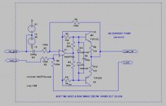
if anybody has the time, and a 10 ohm 10 watt resistor, i'd be interested in seeing the results of experiments on anything anybody reading this has time to try. it's real simple..... using a signal generator and an oscope, apply signal to channel "A" of an amplifier and set the volume for 10Vp-p out. with no signal in channel "B", connect the 10 ohm resistor between channel "A" and "B"'s speaker hots, and use the scope to read the resulting waveform at channel "B"'s speaker terminal. this may seem like a crude way to do it, but you ARE feeding 1Ap-p into channel "B"'s output, and the resulting voltage has a 1:1 relationship with the impedance.
Pioneer receivers average about 70-80 milliohms (some as high as 100 milliohms) at 200hz
Denon receivers (with almost identical construction as the Pioneers, and the same output devices) average around 100-120 milliohms at 200hz.
one Yamaha amp surprised me (RX-V371, the low end receiver) with it's Sanyo STK packs measuring at 30 milliohms at 200hz.
there is a Denon in the shop i have to do an amp rebuild on, and it has a different topology, cascaded diff amps and a current mirror for the VAS. it will be interesting to compare this one's performance to the "average" Denons that use a bootstrap load for the VAS instead of the current mirror.
doing a check on impedance vs frequency was interesting, but i've only done it on a couple of Pioneer amps. generally the feedback turnover frequency seems to be between 500hz-1khz, the amps i did this test on were at about the impedances i listed above, rising to about 500milliohms by the time i got to 10khz. i think part of the reason the 200hz figures are so high, is internal wiring and relay contacts. these measurements are done at the speaker plugs, not at the amp itself, and the Yamaha may use shorter/thicker traces on the amp board, and better relays.
if anybody has the time, and a 10 ohm 10 watt resistor, i'd be interested in seeing the results of experiments on anything anybody reading this has time to try. it's real simple..... using a signal generator and an oscope, apply signal to channel "A" of an amplifier and set the volume for 10Vp-p out. with no signal in channel "B", connect the 10 ohm resistor between channel "A" and "B"'s speaker hots, and use the scope to read the resulting waveform at channel "B"'s speaker terminal. this may seem like a crude way to do it, but you ARE feeding 1Ap-p into channel "B"'s output, and the resulting voltage has a 1:1 relationship with the impedance.
- Status
- Not open for further replies.
- Home
- Amplifiers
- Solid State
- Solid State Testing- Tug of war