Yeah, source followers sometimes oscillate like crazy...
Speaking of pictures, I use irfanview software, it's free and convenient.
Speaking of pictures, I use irfanview software, it's free and convenient.
Voltage Regulator
Thanks guys,
Actually i'm so busy here in the company that i even couldn't relax at home and put my amp pictures....
Anyway thanks for the ideas....
I'll try to do it tonight at home...
I have lot of questions but let's start with this: Do you guys know why DYNACO ST-35 suggests to keep 360V over the EL-84 tubes ? Am i wrong or the max voltage is 300V ?
Luiz
The max plate-to-cathode voltage is 300V, a rating which is more often honored in the breach. As others have mentioned, in the real world, that rating is less important than the screen-to-cathode and plate/screen dissipation ratings. My SCA35 ran the same set of output tubes for 20 years at well over the 300V rating and the tubes still test fine.
Voltage Regulator
Hey here we go...
Ok,
The problem is that in my amp i have my bias in 35ma for each EL-84 set ok, but I change the hole set of output tubes because the tubes tust burn a month ago, then i decide to chenge the hole set and investigate what was happening. Then after a while i realize that the g2 to cathode i found 370.8V and anode to cathode 367.3V
This is the second set of tubes that i have working without regulation. So this is the reason I'm planning to get the regulator.
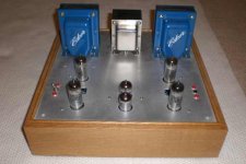
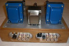
Here i go with some pictures... Thanks for the irfanview software Wavebourn...
Luiz
Hey here we go...
Ok,
The problem is that in my amp i have my bias in 35ma for each EL-84 set ok, but I change the hole set of output tubes because the tubes tust burn a month ago, then i decide to chenge the hole set and investigate what was happening. Then after a while i realize that the g2 to cathode i found 370.8V and anode to cathode 367.3V
This is the second set of tubes that i have working without regulation. So this is the reason I'm planning to get the regulator.
Here i go with some pictures... Thanks for the irfanview software Wavebourn...
Luiz
Attachments

I hate to hijack your thread NBBN, but I also have questions regarding HV regulation. I'm also building an Aikido-based design (just a preamp; will feed a SS power amp until I have the money and time to build a tube power amp).
I plan on using a bog-standard LM317 based regulator with MJE340 pass device, of precisely the sort covered in Jones. My question, though, is this: What sort of filtering is appropriate for the input of a regulator?
My plan is to use a CLC (50uF, 5H, 50uF) filter out of a 5Y3, and then regulate down to 295V with the LM317. But I'm not sure how much hash the 317 can put up with, and whether choke filtering the input is an unnecessary waste of iron.
I've built three Aikidos using the Maida reg. I also use it on my own line stage. Works fine in that application. You have a constant current draw and high noise immunity, so the iron really is a bit wasted. Spend the effort on good common-mode filtration of the heaters, one place this circuit can be a bit vulnerable.
Rad. That simplifies things somewhat. Thanks, SY!
I was worried about running close to the dropout voltage of the 317 (hence the 295V choice), but without the choke dropping any volts, I don't think that'll be a problem.
I'm getting excited.
I was worried about running close to the dropout voltage of the 317 (hence the 295V choice), but without the choke dropping any volts, I don't think that'll be a problem.
I'm getting excited.
Careful which of MJ's implementations you use. All the examples in the amp circuits are correct, but the one taken from National Semi has a zener voltage which is too low, causing the regulator to drop out under load.
voltage regulator
Hi guys,
No problem, be welcome to the discussion...
Whell, i change my 4 EL-84 last week for JJ and the sound seems good. But i didn't have time to work in my regulator...
I plann to use the same idea that Wavebourn said with LM317. I don't plann to use that choke neither...
Last week i found this subject and the circuit seems to work too.
http://www.planetanalog.com/showArticle.jhtml?articleID=174900405
Luiz
Looks like you're wasting a lot of current in the divider chain, and that equals quite a lot of heat. Make sure your pot is up to the task.
I'm using 1k/220K, for two reasons:
1- MJ does it, and If It Ain't Broke, Don't Fix It
2- I had the proper resistors handy.
You should do well to note that ideally, the bias chain draws 5mA, 5mA being the minimum load current for the LM317 to regulate properly. A particularly astute observer will notice that 221k across 300V equals ~1.358 mA.
MJ solves this by preheating the tubes. I solve it by including a separate 80k divider for heater bias. I expect that there's another place you could use this current, besides setting your output voltage.
Do note that as of last night this regulator is still under construction, and may yet go "pop!" or fail to be satisfactory really at all.
--k
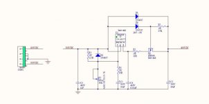
Here is the schema of my amplifier power supply with solid state regulator for the input tubes:
An externally hosted image should be here but it was not working when we last tested it.
Voltage Regulator
Hey koolatron,
Thanks for the idea...
But let me see if i've got the info.
You are telling me to change the R3 to 1K and use the 220k for pot R5?
Is it right ?
I liked your sch Antonio, but i'm really thinking in going ahead with LM317 because i already have at home and also the IRF840.
So i'm planning to have this little board, then i can use in another amp that i'm planning to build with KT88.
Thanks,
Re: Voltage Regulator
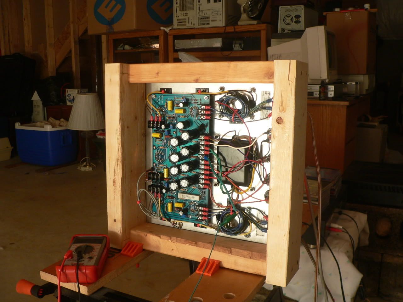
Nice looking DIY ST-35 you have there. Is that a Rev C, or a Rev D? Did you assemble it yourself? I especially like your chassis. It's quite a bit more professional looking than the construction grade pine 2x4 that I used.
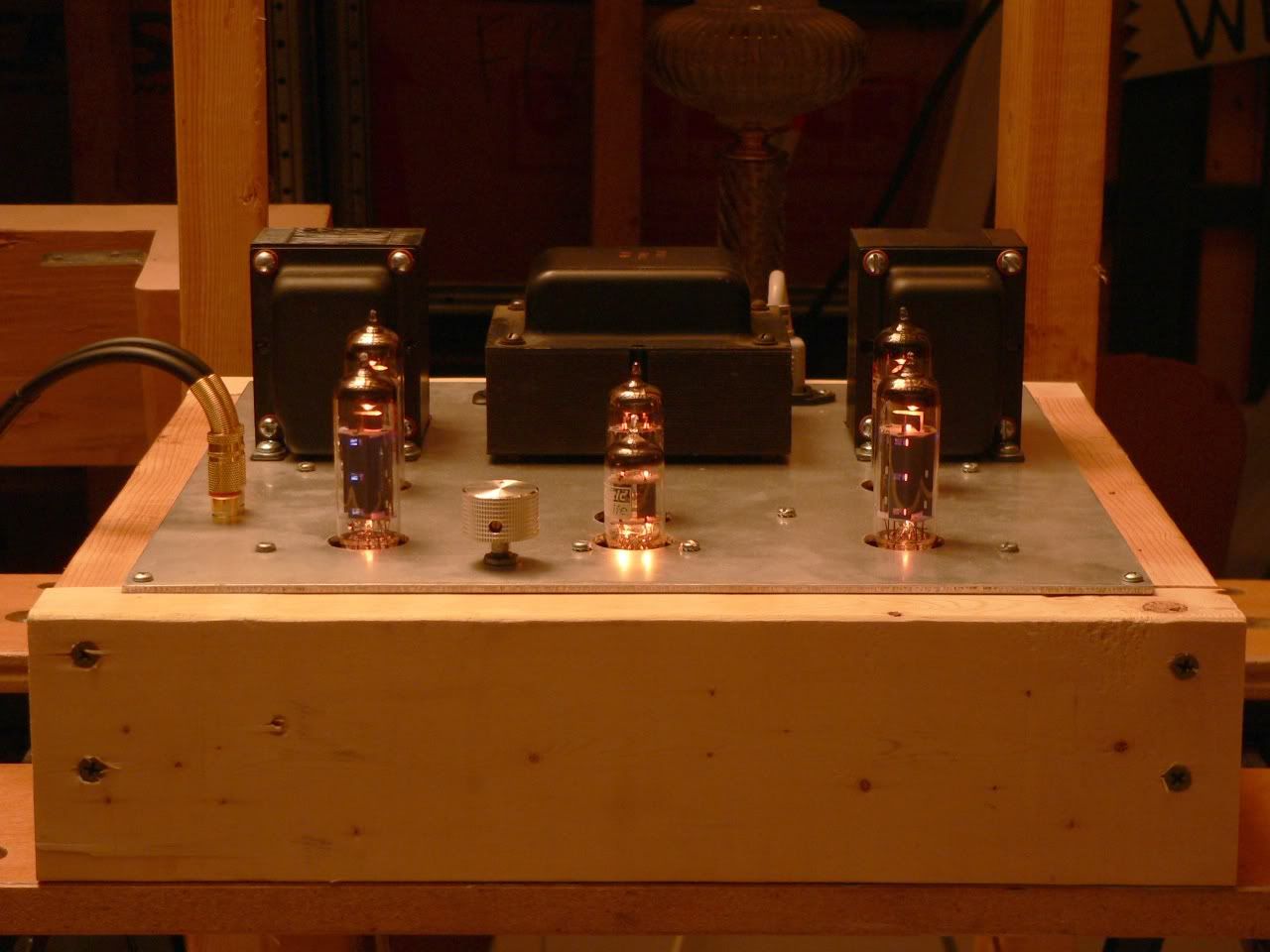
I will say I haven't had any problems with the voltage on mine, and it runs over 400 volts most days. I've had the same set of Reflektor 6p14p in it since last July, and they appear to be holding up well.
NBBN_amplifiers said:Here i go with some pictures...
Luiz
Nice looking DIY ST-35 you have there. Is that a Rev C, or a Rev D? Did you assemble it yourself? I especially like your chassis. It's quite a bit more professional looking than the construction grade pine 2x4 that I used.

I will say I haven't had any problems with the voltage on mine, and it runs over 400 volts most days. I've had the same set of Reflektor 6p14p in it since last July, and they appear to be holding up well.
Pictures
Hi Ty_Bower,
Thanks,
Ual seems that you have the same revision that i have witch i think it's D, the last one.
I did everything by myself. I bought the chassis on e-bay, but it tooks me more than 1 month just researching for a really good one.
I was going thought all math for this amp and seems that we have to keep 300V to the EL-84. The Dynaco says to keep around 360, but to be around 12W as the datasheet shows and going to the load line we easily see we are out. Also the output power is around 9.29W in this situation with higher voltage.
Am i wrong ? This is the second time i'm changing my EL-84's and i think it's because of that.
How long do you have your amp ? Don't you have any problem with that ? Which voltage are you running yours EL-84's.
Take a look in this web site.
http://www.freewebs.com/valvewizard1/pp.html
Nope. Mine is a Rev B. Look closely at the top, there's eight screws mounting the circuit board, not six. The Rev B is a bit larger, and the underside is different too.
Your chassis looks a lot like Uncle Ned's TubeZone chassis, but your iron is all different. I thought he usually sold a toroid PT and a set of Z-565 clones with that chassis.
I've found the maximum power depends somewhat on your output transformers and what frequency you are trying to reproduce. My amp started out with a set of Hammond 1620 transformers, and they were only good for three or four watts before they started to show noticeable distortion on the oscilloscope. I've since swapped in a better set of transformers and they make a lot more clean power much lower.
Re: Pictures
Sorry, I missed your last few questions. I've had this amp running since last July. My power transformer isn't the one spec'd in the manual, and it tends to run the plates of the 6p14p tubes at a little bit over 400 volts. I was a bit worried at first, but I haven't had any problems with it so far...
NBBN_amplifiers said:How long do you have your amp ? Don't you have any problem with that ? Which voltage are you running yours EL-84's.
Sorry, I missed your last few questions. I've had this amp running since last July. My power transformer isn't the one spec'd in the manual, and it tends to run the plates of the 6p14p tubes at a little bit over 400 volts. I was a bit worried at first, but I haven't had any problems with it so far...
Re: Pictures
I'm fine with single ended designs, but no good at working out load lines for push pull stages. According to the data sheets, a pair of 6BQ5 tubes are good for 11 watts at 250 volts, and 17 watts at 300 volts. I'd wager you might be able to eek even more power out of them at the higher voltages used in the Dynaco design. The data sheet is here:
http://www.nj7p.org/Tube4.php?tube=6BQ5
As others have said, some tube ratings can be taken with a grain of salt. Just ask the guy from TubeLab. I'd be more concerned with plate and screen dissipation than absolute voltage.
NBBN_amplifiers said:The Dynaco says to keep around 360, but to be around 12W as the datasheet shows and going to the load line we easily see we are out. Also the output power is around 9.29W in this situation with higher voltage.
I'm fine with single ended designs, but no good at working out load lines for push pull stages. According to the data sheets, a pair of 6BQ5 tubes are good for 11 watts at 250 volts, and 17 watts at 300 volts. I'd wager you might be able to eek even more power out of them at the higher voltages used in the Dynaco design. The data sheet is here:
http://www.nj7p.org/Tube4.php?tube=6BQ5
As others have said, some tube ratings can be taken with a grain of salt. Just ask the guy from TubeLab. I'd be more concerned with plate and screen dissipation than absolute voltage.
- Status
- Not open for further replies.
- Home
- Amplifiers
- Tubes / Valves
- Solid State Regulator for tube amp