I think the OP was actually looking for more or a better profile of the distortion in the DX Trust. Perhaps a "better" design is not really what's wanted.....why not pick one of those...
hi guys,
I was looking for a nice projects for my "opera" loudspeakers.
I have tried many solid state amps (from 50 to 150W rms) but they are too powerful for my room and lossy for my taste. No detail or scene...
Can you suggest a very very good little diy amp (20-30w max) which has awesome quality and detail?
regards
Modulus 86 with a +/-15V power transformer. See Neurochrome.com
Modulus 86 with a +/-15V power transformer. See Neurochrome.com
That should be a 15-0-15V power transformer, for around +/-20V supply rails.
I think the OP was actually looking for more or a better profile of the distortion in the DX Trust. Perhaps a "better" design is not really what's wanted.
yes, it's exactly what I'm looking for.
I think that if someone looks at dx trust schematics, can surely improve it.
I would start from R13.....
You can easily improve the electronics but you are talking about sonics. The distortion profile is not something we can predict closely from a schematic unless we have the amplifier and with same parts types in front us and are able to tinker with it and test with a spectrum analyser or simply listen by ear, as everyone does and is the universal, though unreliable test method.
You could also simulate the circuit for approximate results and make changes accordingly, taking care not to stray into danger with parts ratings, stability and issues with bad part models, which are legend on free simulator programs. That still requires a prototype to be built for a reality check anyway.
Destroyer X has the design experience for the Trust amplifier's sonics so the best person to ask is Carlos himself, on his thread, if he's interested in revisiting the design.
As you look about threads here for something along your ideas of audio, you should also visit Hiragas 'le monstre' and 20W class A amplifier threads. Jean Hiraga's ideas probably coincide with your preferences and he does go to lengths to explain what it means clearly.
Here is the original article from 'le audiophile' on The Class A audio Site, now hosted by Rod Elliott's ESP site. I don't know where you would get the original French or Italian versions. The Class-A Amplifier Site - Hiraga 'The Monster'
I think you would be very happy with the sound from Ranchu/Aksa's quasi MOSFET/BJT amp. I have used it with dual 25v rails and it sounds superb. Great detail, nice harmonic profile. Easy to build now that bugs have been worked out. My latest is with Dacz layout.

http://www.diyaudio.com/forums/soli...mentary-mosfet-amplifier-151.html#post4859870
http://www.diyaudio.com/forums/soli...mentary-mosfet-amplifier-151.html#post4859870
That should be a 15-0-15V power transformer, for around +/-20V supply rails.
+1. There is are two threads on DIYAUDIO, including a build thread. Here is his website link which has all measurements and details: www.neurochrome.com; my build is included in that link.
Best,
Anand.
I have a lot of respect for the designer of the mod86 and have been told it's one of the best sounding amps at any price that you can buy. But just a note that the mod86 is *significantly* more expensive (the bare PCB's alone will set you back for the cost of several discrete class AB amps from this forum if Gerbers see free). It is more complicated to build, and I have heard from a trusted source who has built several of them - not better than a very simple but good class AB MOSFET amp in this forum from Apex Audio. An integrated IC amp will not have the current carrying capability of a dedicated high power audio grade. BJT or MOSFET output stage.
Last edited:
Do you a nice present ...construct and listen a P3A even if you don't like it costs nothing to make even point to pint to get an idea if this works then you make a better make .
JM
you are wrong smaller amplifier can have safer bandwidth and better speed when you grow on power you cannot have these factors free you need to guard the amplifier more ..
JM
you are wrong smaller amplifier can have safer bandwidth and better speed when you grow on power you cannot have these factors free you need to guard the amplifier more ..
Low cost and easy to build amplifier: Emprit Amplifier.
Low and mid better than LM1875, but high slightly more "bright". Better overall than LM1875 if use for reproduction complex music or "fast" music.
Low and mid better than LM1875, but high slightly more "bright". Better overall than LM1875 if use for reproduction complex music or "fast" music.
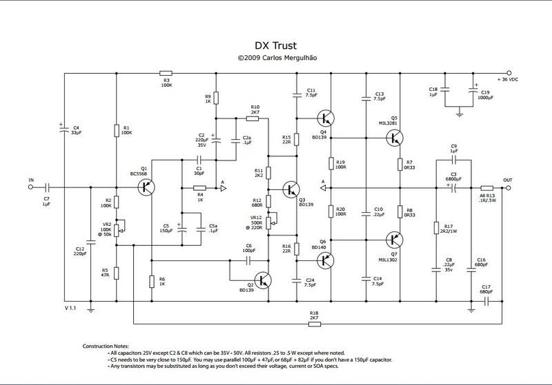
Okay, the DX trust is a single supply full complimentary amp, with a speaker capacitor.yes, it's exactly what I'm looking for.
I think that if someone looks at dx trust schematics, can surely improve it.
I would start from R13.....
R13 is a cheap, available off the shelf RF interference inhibitor to keep radio emisions from sending your amp into oscillation. 5 W wirewound resistors typically have some inductance due to the windings. If you want something more conventional, get some 16 or 14 ga magnet wire. Wind 14 turns around a AA battery, remove the battery. Parallel it with a 10 ohm 3 watt resistor. Voila, zobel network like most real amps have. My PV-1.3k has exactly that for a zobel network.
The speaker capacitor design is something I highly recommend for newbies for their first amp. When a solder joint lets loose, instead of rail voltage toasting your speaker, The amp sits there putting DC on the capacitor, which can stand it. A direct comparison of my improved ST120 (bias correction) speaker cap amp versus a no caps in music flow CS800s, at 1.5 Vpp, I can't hear the difference.
I think you are looking for an amp not particularly with less power, but you need less gain so the amp is not so loud. Gain has to do with ratios of resistors around the voltage gain stages. I just built a very similar Apex AX6, point to point hand wired, no printed wire board. It is quasi comp. I used 2n5401 input, D44R2 VAS, TIP41/42C for drivers, NTE60 (MJ802 white box) for outputs. I needed higher voltage transistors than this dx trust because my transformer puts out 80 vdc @ 6.5 A. I listen to classical source, so even with a 1.5 Vpp base level output, I can get a 20-40 v peak on the cannon shot in 1812 overture. If you listen to singer songwriter guitar sources, the dynamic range is not very high and a 36 v power rail could be fine at 1.5 Vpp average lintening level.
Also on DX trust, I'd put 20-30 pf disk cap to analog ground at the input to keep RF out. I have trouble with CB radio cars driving by, and lamp dimmers. I'd also use a 4.7 uf input cap instead of 1 uf, it doesn't cost more.
C13 & 14 are a little strange, and would tend to increase the tendency of the output transistors to not shut off quickly. Look at the Apex AX6 for comparison. Similar amps are the Elliott basic 50 (npn input), the TGM8 and with more sophisticated input structure, the Panasonic SU380
Last edited:
Many thanks, this is a good starting point...
I will try your suggestion and anyother one is welcome
I will try your suggestion and anyother one is welcome
dx trust has too many goofy capacitors.
C12 would tend to short out your input voltage. Delete it, or substitute 33 pf as I said (or 22 to 47 pf).
Delete C10, C13, C14, C16. He may have had an oscillation problem, but these are the wrong places for these. C11 & C24 are more conventionally 47 pf instead of 7.5 pf to prevent oscillation. These are disk caps. Part of Mergulhao's oscillation problem may have been the lack of 10 ohm resistors between the drivers Q4 & Q6 and the output transistors bases Q5 & Q7.
C3 could be 4700 uf or 3300 uf which is a lot cheaper.
Really, AX6 is a much more proven design. Worked out for 56 v supply though. My AX6 is not oscillating, I checked with a VOM 2.5 vac scale on the output with the input shorted. 0 v out.
Also look at kurozz first amp http://www.diyaudio.com/forums/solid-state/297453-tips-first-amp-design.html but follow the suggestions in the text, the first draft had some problems. This hasn't been built to my knowledge but the idle bias control is better worked out than AX6. My Ax6, if I set the idle current (through output emitter resistor like R7 dx) to 8 ma quiet it peaks at about 160 ma with some volume.
On dx trust, VR2 is adjusted to get the DC input voltage of the output capacitor C3 to the middle of the supply voltage. AX6 this control is missing, I had to change R2 several times to get the output centered. I ended up with 270k pull up 300k pull down with a high gain On semi 2n5401 input transistor.
I build on Nema CE laminate board (garolite from mcmaster carr) that I drill with a #46 (about .5 mm) drill. Canvas/phenolic laminate, about $20 a 30 cm x 60 cm sheet. I saw it up with a hacksaw. With point to point you could have this built up in a couple of weeks without learning how to etch boards or buying a layout program. (I can't keep printers from clogging up the cartridge jets) Teflon or kynar insulated wire helps prevent insulation burns when waving the soldering iron around. My output transistors are over on a separate heat sink with the board screwed to it. My board is only 9 cm x 14 cm.
Best of luck.
Last edited:
dx trust has too many goofy capacitors.
C12 would tend to short out your input voltage. Delete it, or substitute 33 pf as I said (or 22 to 47 pf).
Delete C10, C13, C14, C16. He may have had an oscillation problem, but these are the wrong places for these. C11 & C24 are more conventionally 47 pf instead of 7.5 pf to prevent oscillation. These are disk caps. Part of Mergulhao's oscillation problem may have been the lack of 10 ohm resistors between the drivers Q4 & Q6 and the output transistors bases Q5 & Q7.
C3 could be 4700 uf or 3300 uf which is a lot cheaper.
many thanks.
What you say, may explain the oscillation I had when zobel network was 2R2+22nF?
If your DX truxt is built up, try putting grid stopper 10 ohm >1 watt resistors between drivers and output bases. Mooly said that was all it took to get a leak delta 70 to stop oscillating with new fast (2 mhz) output transistor instead of OEM 400 khz ones.
Most of the other 6 transistor or 7 transistor designs have 50 to 100 pf base to collector on the driver transistors, and 100 to 400 pf on the VAS base to collector. All disk caps. Dynaco had to add the 50's to the ST120 as part of the "TIP mod" 4 years after initial production.
However, long parallel runs between inputs and outputs can increase tendency to oscillate. My rat's nest 3D point to point wiring cuts the capacitative coupling between various wires, compared to poorly laid out PCB's.
Pick up the Pass F6 kit for sale in the DIYAUDIO store, you won't be disappointed, greT amp, simple build.
PJN
PJN
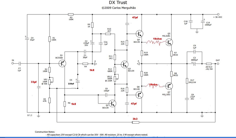
so, thanks to indianajo suggestions, this should be new improved schematic for dx trust amp.
what do you think about it? any help will be appreciated....many thanks
what do you think about it? any help will be appreciated....many thanks
Much more conventional.
Change C6 to 100 pf from 100 uf.
Move the 33 pf from the base of Q1 to outside the 1 uf to ground. It should connect directly to the RCA jack input. The 1 uf input cap can be 4.7 uf.
See post 196 of this thread for the Apex AX8. It is very close to this, plus Mr. Slavkovic builds them at least once. There ought to be a pcb layout somewhere, but not on this AX6 thread. The MJE340 in the upper left corner and associated parts are a soft start I think and are not necessary. See AX6 for the simple version of this area. The output area of your schematic with the zobel and permanent RC load are more stupid proof; IMHO, my ST120 with TIP mod has those. http://www.diyaudio.com/forums/solid-state/236256-retro-amp-50w-single-supply-20.html
Last edited:
(ahem)....C6 is the Miller frequency compensation cap. 33-100pF is normal in most linear amplifiers, 100uF is definitely not.Much more conventional.
Change C6 to 100 pf from 100 uf....
DX's "goofy" capacitors are all about tweaking the sound quality for his audio tastebuds. i.e. enhancing the harmonic distortion to have low order dominant evens. This is no generic design for efficient, clean sound or textbook simplicity so if you don't want the tweaks, look elsewhere to even simpler solutions like JLH's class A designs or Rod Elliott's DoZ - these are great sounding, widely used and simple class A designs.
Mind the heat even at 15W in class A though - you need bigger heatsinks than you think or cast iron fingers and a strong airconditioner in summer. 😀
- Status
- Not open for further replies.
- Home
- Amplifiers
- Solid State
- solid state diy amp 20-30w high quality