Like in old times, just pour molten Beeswax into the chassis to firm things up. Can melt it out again for repairs, if needed.
You make a habit of this sort of thing, don't you? 😉
Milen,
Apology if my previous post (#48) appeared to be rather flippant; I was caught just a mite off-guard about the logic regarding mechanical vs. solder importance for good electrical conductivity.
Let me just say that I have been round the block a few times, some of my professional experience also involving hi-tech applications. No, (properly) soldered joints cannot make any difference in audio (negatively so, I mean). As said mechanical mounting cannot avoid compromise to soldered joints (the mechanical 'elasticity' is more than that of solder so it would crack anyway). Where the mass of the component might be a factor one clamps it securely on the substrate; mechanical 'security' by twisted wire only, goes only so far as hinted at by DF96.
[About the glue: Again said in light-hearted vein, but one does get epoxies which can tolerate well over 100° C.]
Last edited:
There is a solderless kit out there:
Solderless High Impedance Audio Amplifier Kit 1 – Mike's Electronic Parts
Solderless High Impedance Audio Amplifier Kit 1 – Mike's Electronic Parts
The idea itself is pristine, because solder is a bad conductor. So its good to eliminate all the connections that are being made from solder between the conductor and the terminal wire.
But all that has thought deeply in the very beginning of audio and electronics.
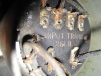
Western Electric did it (and some others, too). They wrapped each internal wire around the terminal of the component and only to fix it, they solder it. Do you get the idea behind it?
To wrap the copper conductor around the terminal pin makes a very close contact between both, wire and terminal. The gear has to function without solder, the solder is just to fix this joint against lossening over time.
Thats the way I build all my gear, but, its nature is a much higher building effort than to solder a wire by holding it against a component and make a gluening connection. Thats what most DIY people think soldering is about. And that it, because they have never learned it and they have never thought about the problem that solder is a bad connector.
I see it all the time when viewing DIY components. And thats the problem with PCB boards, too. Not one parts connection can be made this way. Everything is just put in the holes of the board and then fixed by solder wire. Not an ideal solution, but a cheap one.
And thats the reason why this method was invented by industry for cheaper and mass market production. For me, just the best will do. And thats wrapping and fixing by solder.
But all that has thought deeply in the very beginning of audio and electronics.
Western Electric did it (and some others, too). They wrapped each internal wire around the terminal of the component and only to fix it, they solder it. Do you get the idea behind it?
To wrap the copper conductor around the terminal pin makes a very close contact between both, wire and terminal. The gear has to function without solder, the solder is just to fix this joint against lossening over time.
Thats the way I build all my gear, but, its nature is a much higher building effort than to solder a wire by holding it against a component and make a gluening connection. Thats what most DIY people think soldering is about. And that it, because they have never learned it and they have never thought about the problem that solder is a bad connector.
I see it all the time when viewing DIY components. And thats the problem with PCB boards, too. Not one parts connection can be made this way. Everything is just put in the holes of the board and then fixed by solder wire. Not an ideal solution, but a cheap one.
And thats the reason why this method was invented by industry for cheaper and mass market production. For me, just the best will do. And thats wrapping and fixing by solder.
Attachments
Last edited:
I find the idea of a solder-less amplifier very attractive. I have some experience with crimping computer network cables many years ago the RJ-45 and it is funny how many companies rely on a non-soldered connection to carry their most valuable transactions and data.
No-one has brought up the fact than many of the critical connections in a Hi-Fi audio system are in fact solderless - the RCA or newer connectors from Pre-Amp, to Amplifier, with your CD and turntable also connected using wire. Speakers are connected using solder-less connections, even the most expensive ones. Apparently they work fine.
I had one of those electronic kits many years ago, and it consisted of springs used as contacts, very convenient and useful. I connected up a transistor radio and later built the same thing out with soldered contacts - it worked fine. As of late, though, I am going to try to build without any soldering at all, and lets see the result. I am using the terminal block connectors like the ones in the very first post.
There is a nice kit here:
Solderless Choccy Block Six Transistor MW AM Radio Kit Of Electronic Parts ff | eBay
Solderless project are a great way for a beginner to get into electronics. If there is a failure, you can always easily remove and replace the item. Of course the screws have to be not stuck.
Please consider also galvanic corrosion ( Galvanic corrosion - Wikipedia ) when doing this kind of solderless connections.
Also, be aware of gold plated RCA or speaker connectors:
Galvanic corrosion of electroless nickel/immersion gold plated non-permanent electric contacts used in electronic devices–direct evidence of triggering mechanism - ScienceDirect
Also, be aware of gold plated RCA or speaker connectors:
Galvanic corrosion of electroless nickel/immersion gold plated non-permanent electric contacts used in electronic devices–direct evidence of triggering mechanism - ScienceDirect
The idea itself is pristine, because solder is a bad conductor. So its good to eliminate all the connections that are being made from solder between the conductor and the terminal wire.
But all that has thought deeply in the very beginning of audio and electronics.
Western Electric did it (and some others, too). They wrapped each internal wire around the terminal of the component and only to fix it, they solder it. Do you get the idea behind it?
The main idea is, when you are making series of electronic equipment, first wrapping the wires, after that - visual inspection and in the end soldering is speeding up your work more than twice. All the pads are designed for fast wiring and that you see is the only way to be done. If you look at the military or avio radios, you will see completely different design of the pads - also wires are wrapped, but not optimized for fast wrapping. In the most cases all the cables are in cotton and then pvc or rubber... and they can work in fire with all the tin melted and leaked down
If you look at the military or avio radios, you will see completely different design of the pads - also wires are wrapped, but not optimized for fast wrapping.
I am not sure I understand you regarding military electronics or avionics. I would imagine that for quality control purposes it is better to test the quality of the connectors in a factory and rely on the quality of the connection process (crimping, plugging in ) to ensure that connections are secure. I would not want a mechanic fooling around with a soldering gun inside an avionics bay, not that I have seen one. I have, however seen my car ignition harness, and it has worked fine so far except I had to have it replaced due to deterioration of the wire itself. Car audio also uses connectors exclusively as far as I know.
The construction and testing cycle is a consideration, with wire tapping prototyping is fast and reversible, but otherwise the beginner hobbyist has a huge advantage in not having to use solder and the dangers (do not breathe in vapor). Troubleshooting will be easier or more difficult, I will have to see what my experience is.
Just about the time you re-check your non-soldered speaker wire connections and your RCA connectors you can check your internal amplifier components. Many of the amplifiers I have used have broken some time or another. Having on soldered components would have been very complex but replacing components may be easier. Who knows.
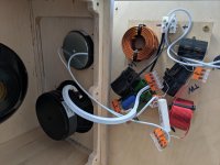
I will be trying Wago connectors for my prototype builds. I use Goop to fix the connectors to a stable surface.
WAGO 221 | WAGO AU
As I get older I have trouble holding a soldering iron steady.
ray
WAGO 221 | WAGO AU
As I get older I have trouble holding a soldering iron steady.
ray
It's a holiday weekend (for US people at least) so perhaps I'm not thinking correctly but how do the Wago connectors help with the small leads on resistors and capacitors?
I can't find photos of my preliminary attempts at using Wago connectors and since we have recently moved from Maryland to Australia, my stuff is on a boat approaching Melbourne. I may be back to building by Xmas.
The Waygo units come in different sizes with 2 to 5 barrels and a common backplane. For example in a five-barrel unit, you can connect four ground wires coming in to a star ground and use the fifth barrel wire as the common ground.
The wires on resistors or capacitors fit quite easily into the barrels and are easy to fix or remove simply by flicking up the lever on the appropriate barrel.
Wago connectors are used by electricians for household wiring where numerous wires need to be connected at a single point. They replace the usual yellow and red twist connectors.
I am recovering from an illness that made soldering difficult and I was looking for an alternative method of building. Fortunately, I can now solder again but I found the Wago connector idea intriguing and will try it next year. Yes, I could use the white euro connectors or terminal strips, but I like to try different techniques.
ray
That's good to know.
The Wago connections I have used in the past (a slightly different style that uses a screwdriver like tool) seemed to be sized to the wire so I wasn't sure that the ones you linked to could take both the thin lead off of a 1/4 watt resistor equally as well as 20 gauge wire.
I'm interested in this type of connections for a similar reason. As I get older I find that my existing nearsightedness plus presbyopia makes soldering anything in situ harder. Right now I plan to solder my current project but I can see the appeal of moving to solderless construction.
Old age has its disadvantages.
I will still have to solder wires to the tube sockets but alternative ideas are always welcome. One additional problem I had was lifting heavy weights so I continue to look for weight reducing techniques.
ray
I will still have to solder wires to the tube sockets but alternative ideas are always welcome. One additional problem I had was lifting heavy weights so I continue to look for weight reducing techniques.
ray
Wago's are great for crossovers, etc. They make a good firm connection to a variety of sizes, types of wire. I've also used them for a while for home wiring.
I would expect them to work for point to point wiring of an amplifier.
I am not as confident in recent 'similar' looking products by competitors.
I would expect them to work for point to point wiring of an amplifier.
I am not as confident in recent 'similar' looking products by competitors.
Attachments
Old age has its disadvantages.
I will still have to solder wires to the tube sockets but alternative ideas are always welcome. One additional problem I had was lifting heavy weights so I continue to look for weight reducing techniques.
ray
Use octal tubes and you can use a relay socket: https://www.amazon.ca/Octal-Relay-Timer-Socket-Panel/dp/B07F1Y3LNG
There are prototyping boards like this: 9 Pin Tube sockets Experiment boards x1 for tube project diy prototype test bott | eBay but they are expensive.
I must admit that the Wago products are very interesting. Not only for a common earth point, or mains to trafo connections, but especially for the house wiring - I need to fix some cr@p installations done by a so called "electrician".
Use octal tubes and you can use a relay socket: https://www.amazon.ca/Octal-Relay-Timer-Socket-Panel/dp/B07F1Y3LNG
There are prototyping boards like this: 9 Pin Tube sockets Experiment boards x1 for tube project diy prototype test bott | eBay but they are expensive.
Both sockets are out of the main idea to avoid the solder joints... they have two more solder connections before the screw one.
- Home
- Amplifiers
- Tubes / Valves
- solderless amplifier?