Hi,
10r suits Eva's very large load and necessarily high fuse value.
3//50r resistors will suit a smaller fuse value (maybe 1000VA to 2000VA).
2//50r resistors will suit about 600 to 1000VA.
Users with 110/120Vac will require surge resistors of about half these values.
If one were to close rate the mains fusing then higher values of resistor would be more suitable.
eg. 800VA transformer fused @ T3.1A starts reliably with 50r (100W) on 240Vac mains.
Re: CMOS ic with power-on reset
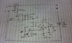
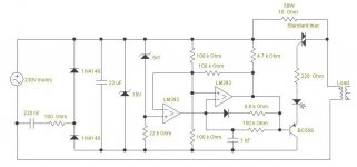
A single CD4541 can't simultaneously provide the turn-on delay and the square wave with only 5% to 10% duty cycle required for triggering the triac. A simple LM393 comparator does.
gmphadte said:If people knew CD4541...
A single CD4541 can't simultaneously provide the turn-on delay and the square wave with only 5% to 10% duty cycle required for triggering the triac. A simple LM393 comparator does.
I 've just prototyped this and wil add it to my amp.
I love simplicity and elegance and can now halve the mains fuse values adding further protection.
Cudos, Eva.
I love simplicity and elegance and can now halve the mains fuse values adding further protection.
Cudos, Eva.
it is for my 300VA torroid on my SKA150.
I am in bed with 'flu ATM and can't be a**ed to get up and check, but I think I doubled the SB fuse to 2A from 1A as it would be blown after 5 or so switch-ons.
I am in bed with 'flu ATM and can't be a**ed to get up and check, but I think I doubled the SB fuse to 2A from 1A as it would be blown after 5 or so switch-ons.
What about use a light bulb as the soft start resistor? It might be cheaper and will probably be safer.
star882 said:What about use a light bulb as the soft start resistor? It might be cheaper and will probably be safer.
Hmmm... not easy to chose which bulb.
Bulbs have a very high inrush current. Try measuring the DCR of one with a meter and calculate what that current is.
Hi,
the light bulb makes an excellent test kit due to it's ability to take full mains voltage without failing.
Unfortunately, it also has a positive temperature coefficient.
As demand for power in the amp goes up, the resistance goes up, reducing the voltage available to the transformer.
A -ve temp coef is needed for soft start duty.
At start up the cold resistance is high and limits initial current to your selected value. The passing current heats the resistance and causes it's value to fall, allowing more current to pass.
After a few seconds the start value will have reduced by a factor exceeding 10. Say 5ohms down to 0.3ohms. This allows the amp to run with almost full voltage available to the transformer.
An alternative is to use a resistor with a near zero temp coef. This must be bypassed very quickly to prevent the resistor overheating. That is the circuit discussed in this thread.
Keep the light bulb for it's testing use.
BTW,
that +ve temp coef is useful for tweeter protection.
I was wondering whether a mains (coil) rated relay/contactor will serve the purpose with the resistor across N/O contacts. After all it takes time to make the contact.
Gajanan Phadte
Gajanan Phadte
Hi,
look up the AC relay data to find the time to close.
I suspect only a maximum is quoted and it could be around 10 to 15mS.
At best that would allow less than one mains cycle to pass through the surge suppressing resistor.
The info I have seen, suggest the toroid needs three to five cycles to fully establish it's magnetic flux. That's why I design for around 300mS delay on the relay.
I designed an LLC SMPS using a PIC.
Using a PIC gives good control over power up.
I first wait until power supply caps are charged up (uses thermistor to limit current)
Then I use a soft start to limit current draw setting LLC frequency very high.
Only then do I start regulating the voltage.
Using a PIC gives good control over power up.
I first wait until power supply caps are charged up (uses thermistor to limit current)
Then I use a soft start to limit current draw setting LLC frequency very high.
Only then do I start regulating the voltage.
Mooly,
are any of Eva's pic held somewhere, that they can be retrieved and inserted back into his posts?
are any of Eva's pic held somewhere, that they can be retrieved and inserted back into his posts?
No, those pictures aren't held by the forum, they were external links. I saved it at the time because I thought it looked interesting.
- Status
- Not open for further replies.
- Home
- Amplifiers
- Power Supplies
- Soft-start circuit with no relays and no aux. transformers