- possibly, not "at the peak" but at the zero (or closer to the zero). Because inrush current is lagging on the primary voltage.
The current in an inductor lags the voltage by 90º, so you get the highest inrush current if you turn the power on and the zero crossing.
Tom
I recommend that you disregard/abandon Figure 5 of ESP's general article about soft start, and instead focus on the actual ESP project 39, specifically its Figure 6, shown below. In that circuit (which is on the PCB that Elliott actually sells), delay time is set by R1 and C2. I recommend using a 20 turn trimpot for R1, that way you can adjust the timing according to YOUR tastes, instead of Rod Elliott's tastes.
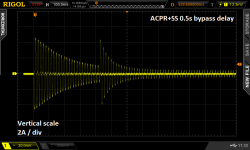
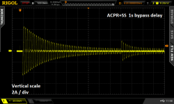
Here are a couple plots of current at turn-on, with an inrush current limiter that includes a bypass relay. They show what happens when bypass is engaged, and what happens when you vary the timing of the bypass. Of course, your transformer and your ICL resistors/thermistors and (to a lesser extent) your filter capacitors, will be quantitatively different: different peak current, different decay time, different post-bypass peak current. But the overall shapes, the "envelopes" shown below, are representative of the general situation.
_
Attachments

Last edited:
Look at the BOSE 1800/1801 I series ... huge transformer (1,2kVa) ww resistor , huge relay ... One resistor failed cooked on one , i changed both with 15w Dale 😉
Last edited:
Here are a couple plots of current at turn-on, with an inrush current limiter that includes a bypass relay. They show what happens when bypass is engaged, and what happens when you vary the timing of the bypass.
_
Well, you didn't consider the magnetic inrush current of the transformer and the saturation, which is a multiple of the charge current of the caps.
When there is saturation up to 90A are flowing through the primary.
And that is the main reason why an inrush current limiter is applied.
The inrush current of 2x22000uF cap at 2x22V will be around 12A primary with a 400W toroid without soft start and if the diodes can stand the secondary 70A peak current in the first half wave no problem.
Also the amp is muted by the speaker relay, so only 100mA bias is consumed. the soft start has to be finished well before the speaker is connected.
A few words to the resistor. I simulated with 7 ohm and 30 ohm
7: peak inrush 20A, peak power 500W, rms power 58W for 300ms
30: peak 6.8A, 150W, 20W for 500ms
bansuri, attachments 2 and 3 on post #23 are screen captures from a Rigol-brand digital oscilloscope. The oscilloscope was connected to a current probe (sensitivity: 2 amperes per vertical division) that was measuring the AC mains current of a class-AB audio power amplifier at switch-on. The power amp was equipped with a soft start board. Thanks to the soft start, peak inrush current has been limited to 4.4 amperes.
Those attachments are measured data from real-life hardware; they aren't simulations.
The reason why you don't see "magnetic inrush current of the transformer" is because the soft start board has limited it. That is the board's job after all: it's an inrush current limiter.
The purpose of showing those two real-life measurements of current-vs-time, was to demonstrate what happens at the bypass event. The bypass event occurs when the soft start is terminated ("bypassed"). At that instant, AC mains current jumps up, and if you arrange your circuit timing correctly, you can make the up-jump smaller than the initial inrush.
would have been nice to see a graph without the limiter for comparison.
That is what I wanted to add.
That is what I wanted to add.
There it is : post#1
PCB: low voltage On-Off switch drives AC mains relay \ includes soft start .. H9KPXG
PCB: low voltage On-Off switch drives AC mains relay \ includes soft start .. H9KPXG
- Home
- Amplifiers
- Power Supplies
- Soft Start Circuit Help