Hi Richard.
For resistors use standard metalfilm types 0,4 -0,6W
That trimmer you pointed to wont fit on the board.
I,ll see if i can make a new BOM with Farnell numbers..

/JZ
For resistors use standard metalfilm types 0,4 -0,6W
That trimmer you pointed to wont fit on the board.
I,ll see if i can make a new BOM with Farnell numbers..
/JZ
zei said:Hi Richard.
I,ll see if i can make a new BOM with Farnell numbers..
/JZ


zei said:Hi Richard.
For resistors use standard metalfilm types 0,4 -0,6W
That trimmer you pointed to wont fit on the board.
I,ll see if i can make a new BOM with Farnell numbers..
/JZ
Hi Zei
I have found everything that I require from Farnell. It’s only the trim pot and a query regarding the resistors.
When you mentioned the board requires 0,4 -0,6W resistors, do you mean some are 0,6W and others are 0,4W, or can I safely use 0,4W throughout the board?
Thanks
Richard
do the calculations and you'll probably find that 250mW will run cool for almost all of them.Tripmaster said:When you mentioned the board requires 0,4 -0,6W resistors, do you mean some are 0,6W and others are 0,4W, or can I safely use 0,4W throughout the board?
Looking good
Did you source all your parts from Farnell? If so what is the total cost. You have not fitted an op-amp, which one do you intend to use?
Did you source all your parts from Farnell? If so what is the total cost. You have not fitted an op-amp, which one do you intend to use?
Puffin said:Looking good
Did you source all your parts from Farnell? If so what is the total cost. You have not fitted an op-amp, which one do you intend to use?
Why thank you...flattery will get you nowhere!
Yeah I did source the parts from Farnell, I am not sure of the total cost for this project as I purchased several other parts for an ill fated DAC project 😉 I will email the Farnell parts list to you.
I am going to use the OPA2134PA as suggested in the BOM.
As I have not tested the circuit, I thought I would leave the OPAMP until last.
That looks great 🙂
If you could be so kind and put the farnell list here in this thread?
Would save me some time . 🙂
/J
If you could be so kind and put the farnell list here in this thread?
Would save me some time . 🙂
/J
zei said:That looks great 🙂
If you could be so kind and put the farnell list here in this thread?
Would save me some time . 🙂
/J
I will post it later 🙂
zei said:That looks great 🙂
If you could be so kind and put the farnell list here in this thread?
Would save me some time . 🙂
/J
Please find attached BOM with Farnell part numbers.
A couple of things to note...
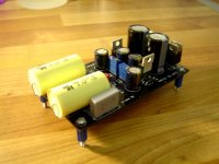
C9 & C10 - The pin spacing is a little bit too wide for the 0.1uf Wima caps so I mounted them flat to the base of the board.
C11 & C12 - The 100uf Panasonic capacitor pin spacing is a little bit wide for PCB holes....you will need to bend the legs closer together.
The pin spacing is correct for all other parts
I hope this helps 🙂
Richard
Attachments
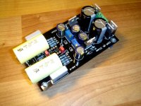
WOW...It worked first time! (Its all in the title)
I have only just applied the power, but on first impressions it doesn't sound bad at all. I will let the components burn-in and report back later.
I also have an OPA2132PA Dual FET op-amp that I may try later.
Thanks Joakim
Richard
I have only just applied the power, but on first impressions it doesn't sound bad at all. I will let the components burn-in and report back later.
I also have an OPA2132PA Dual FET op-amp that I may try later.
Thanks Joakim
Richard
Good job Richard 🙂 Like you say, its all in the title 😎
We are missing pictures though 😉
Puffin, You need help?
/JZ
We are missing pictures though 😉
Puffin, You need help?
/JZ
Puffin said:Excellent news. You can help me with mine.
Why of course my dear friend...how may I be of assistance? 😉
- Home
- Amplifiers
- Chip Amps
- SOAP MKIII (Simple OpAmp Pre) With onboard PSU