Here are the calculated values of arc suppressing snubber R and C, using the famous C. C. Bates equations mentioned in the links of post #11. Typically I use component values larger than these, but then I prefer to handle mains switching very gingerly.
_
Reading off the graph, looks like about 0.5uF (seems high) and 10 Ohms?
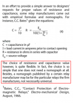
Here are the Bates equations, just plug in "Eo = 230V" and "I = (your number)"
On the other hand, the red paragraph appears to suggest that simply using your gutt, with two T's, {signifying your most primal caveman instincts} is probably just as good. However you don't get to blame Doctor Bates if your gutt derived circuit fails to do the job.
_
On the other hand, the red paragraph appears to suggest that simply using your gutt, with two T's, {signifying your most primal caveman instincts} is probably just as good. However you don't get to blame Doctor Bates if your gutt derived circuit fails to do the job.
_
Attachments
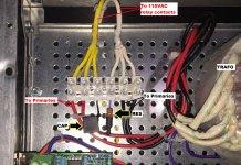
I'm planning to bring a power amp project and put it on the DIY display table, at Burning Amp 2019 in San Francisco. The amp includes an arc suppressor in circuit "position B" as displayed in post #2 up above. The arc suppressor is a film capacitor in series with a 3 Watt resistor. I insulated the leads with heatshrink and then painted them with black dope for extra insulation. Photo below.
_
_
Attachments
R-C snubbers are always a compromise. In many cases a MOV works better. And snubber the inductive (load) component only is often better than across the switch, although you may have inductance in the AC line causing problems.
And we assume the relay coil has a fly-back diode?
And we assume the relay coil has a fly-back diode?
Position B (used here) does connect the arc suppressor across the load. Please see the schematic in post #3.
Bonsai, imagine connecting the series RC in position B rather than position A (schematic in post #3).
*IF* you believe that it will successfully eliminate or reduce contact arcing, snubber circuit in position B has the advantage of zero AC current when powered off.
In other words you won't get a shock off the relay output when its open.
Having the snubber as part of the load has the advantage that it can be
correctly sized for the load.
Problem is the arcing voltage will travel back down the live wire spraying RF interference everywhere, due to the series inductance of the mains wiring. Adding a class X cap across the live/neutral _input_ to the relay should fix this, and it can be part of a line conditioning filter of course with all the benefits that brings.
Of course the position A snubber has a lower component count, but you will need to check what effect the leakage current through it causes to the load - it might partially power up even.
Using a (bidirectional) TVS instead of RC snubber is another approach - I've no idea if they come in class-X and class-Y variants for mains use though.
So, if I interpret correctly..
Snubber position A for circuits without soft start and snubber position B for circuits with soft start that have a respectable start resistance.? I use CL90
Snubber position A for circuits without soft start and snubber position B for circuits with soft start that have a respectable start resistance.? I use CL90
And while I'm at it, I raised the question before in if reversing the order of soft start relays would reduce arcing of the contacts. Pretty sure I was shot down on that, but what is the take here in this thread? Starting the power and removing by ways of the cl90 ?
- Status
- Not open for further replies.
- Home
- Amplifiers
- Solid State
- Snubbing Relay Contacts - A Warning