I have been working on a project in which the mains power is switched by a power relay (16A 250 VAC Tyco). On other products, I've just used a mechanical push-button switch with no problems.
The microcontroller in this most recent case kept on resetting and/or hanging-up randomly. I snubbed the relay drive to increase the rise and fall times, looked at the software etc etc - only a marginal improvement, with random resets or hang-ups still occurring every 5 or 6 power-up/down cycles
Turns out in my haste I never took the trouble to snubber the relay contacts. On the 3.3V controller supply, I was getting +5 to -2 volt spikes, and the same on many of the I/O port lines. The noise spikes - sometimes just one of them, other times 4 or 5 in quick succession about 2-5us apart - arose entirely due to the relay contact arcing when opening and closing the mains to a 500 VA transformer load. Note, the system also has a soft-start consisting of a 10 Ohm NTC which is bypassed after about 1 second.
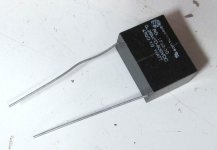
I placed a 0.1uF 630VDC in series with a 150 Ohm 5W resistor snubber across the contacts and the problem is fully resolved. No random resets or hang-ups and all working perfectly.
Moral of the story, if you are switching power with a relay, always snubber the contacts - for both noise and to protect the contacts from arcing.
Separately, the reason why this problem has not arisen on projects that use a switch to apply power is that the contact noise has abated long before the controller comes out of power up reset. However, there is the risk that you could crash the controller on power down, so snubbing ordinary switch contacts if you have a microcontroller anywhere should also be considered.
😎
The microcontroller in this most recent case kept on resetting and/or hanging-up randomly. I snubbed the relay drive to increase the rise and fall times, looked at the software etc etc - only a marginal improvement, with random resets or hang-ups still occurring every 5 or 6 power-up/down cycles
Turns out in my haste I never took the trouble to snubber the relay contacts. On the 3.3V controller supply, I was getting +5 to -2 volt spikes, and the same on many of the I/O port lines. The noise spikes - sometimes just one of them, other times 4 or 5 in quick succession about 2-5us apart - arose entirely due to the relay contact arcing when opening and closing the mains to a 500 VA transformer load. Note, the system also has a soft-start consisting of a 10 Ohm NTC which is bypassed after about 1 second.
I placed a 0.1uF 630VDC in series with a 150 Ohm 5W resistor snubber across the contacts and the problem is fully resolved. No random resets or hang-ups and all working perfectly.
Moral of the story, if you are switching power with a relay, always snubber the contacts - for both noise and to protect the contacts from arcing.
Separately, the reason why this problem has not arisen on projects that use a switch to apply power is that the contact noise has abated long before the controller comes out of power up reset. However, there is the risk that you could crash the controller on power down, so snubbing ordinary switch contacts if you have a microcontroller anywhere should also be considered.
😎
I made some time ago a power supply tester based in Electronic Load and this tool was microprocessor controlled. I used 18F4620 as I had lots of parameters to test and I got the exactly the same issue. The tester changed the AC voltage from 120Vac to 220Vac with snubber in relay contact.
After some time troubleshooting I face conducted noise from switched mode power supply.
Conclusion, we can have some symptom with different causes. Care in trouble shooting makes all difference.
Ronaldo
After some time troubleshooting I face conducted noise from switched mode power supply.
Conclusion, we can have some symptom with different causes. Care in trouble shooting makes all difference.
Ronaldo
Bonsai, what is the pathway that "transmits" or "conducts" or "squirts" noise from the relay contacts, to the 3.3V DC supply rail?
Secondly, have I calculated the off current correctly? With the relay disengaged and its contacts open, the 230VAC mains appears directly across the RC snubber, and an AC current of (230 / (2*pi*fmains*Csnub)) = 7.8 milliamperes flows. Is that right?
_
Secondly, have I calculated the off current correctly? With the relay disengaged and its contacts open, the 230VAC mains appears directly across the RC snubber, and an AC current of (230 / (2*pi*fmains*Csnub)) = 7.8 milliamperes flows. Is that right?
_
Attachments

Last edited:
IMHO: better harden the microcontrollers power supply and reset circuit to avoid sporadic brown out resets. Of course it is a good idea to add extra snubbers to supress EMI ...
Have fun, Toni
Have fun, Toni
Perfectly fine for provisional tests if you have nothing else available, but the final cap should be X-rated: random crashes may be annoying, but a house fire is even worse....I placed a 0.1uF 630VDC in series with a 150 Ohm 5W resistor snubber
Capacitor impedance: Zc = -j(1/wC) where w = 2 * PI * frequency
At 50 Hz the impedance of a 0.1uf capacitor is
-j(1/(2*PI*50*1e-7)) = -j(1/3.14e-5) = -j31830
The impedance of the 150 Ohm resistor is much smaller than
the capacitor impedance so the current is 230/31830 = 7.2mA.
This is a large leakage current and 0.1uF is much larger
than what I have seen across a switch contact. 4700pF or so
is more typical.
Using a DC rated capacitor across a mains connection is not recommended.
Even a 630VDC capacitor will degrade with time due to AC corona.
The capacitance drops as the metallization vaporizes slowly each
time there is an arc inside the capacitor. I haven't seen actual
combustion from the arcing but have seen capacitors degrade to
nearly zero microfarads.
See the thread referenced below.
X-capacitor
Also see the attached technical bulletin from ASC.
Attachments
All good comments thank you 🙂
The 0.1uF 630 VDC and 150 Ohm is all I have to hand at the minute. 400VAC X caps at 10nF and 0.05 uF ordered so I can check them out.
Mark, the hookup is as you have drawn it.
The 0.1uF 630 VDC and 150 Ohm is all I have to hand at the minute. 400VAC X caps at 10nF and 0.05 uF ordered so I can check them out.
Mark, the hookup is as you have drawn it.
Bonsai, imagine connecting the series RC in position B rather than position A (schematic in post #3).
*IF* you believe that it will successfully eliminate or reduce contact arcing, snubber circuit in position B has the advantage of zero AC current when powered off.
*IF* you believe that it will successfully eliminate or reduce contact arcing, snubber circuit in position B has the advantage of zero AC current when powered off.
I have seen that method but don't know if it is effective for contact arcing. Do you have any info about it?
Suggest you look at the attachments to post #31 and #32 (here).
The small signal equivalent circuit treats the "Line" or "Hot" mains wire, to be at the same small signal potential as the "Neutral" or "Cold" mains wire. Thus for small signal analysis, snubber position A is identical to snubber position B. As is drawn in that Illinois Capacitor pdf document. Now all you need to do is decide whether small signal analysis is appropriate for your contact arcing situation.
The small signal equivalent circuit treats the "Line" or "Hot" mains wire, to be at the same small signal potential as the "Neutral" or "Cold" mains wire. Thus for small signal analysis, snubber position A is identical to snubber position B. As is drawn in that Illinois Capacitor pdf document. Now all you need to do is decide whether small signal analysis is appropriate for your contact arcing situation.
Ahh - that's a good reference. I'll go through that carefully - position B is definitely preferred.
Snubber effectiveness is definitely worth checking either way. In the past there have been some cases of suppression caps being mounted in parallel but a fair bit away from the actual switch, and contacts eventually burning up as a result.
Good point. In my case with the ‘B’ position suggested by Mark, the neutral wire is located quite some distance from the switch, so I may have to go for A.
Caps arrive later today, so I’ll try it and put some pictures up before and after.
Caps arrive later today, so I’ll try it and put some pictures up before and after.
Placing a capacitive snubber across what is meant to be an isolating switch is potentially lethal to you and others who may copy.
Plus it does not address the real problem - which is the very high, very short magnetising current pulse into the transformer when first energised. This current pulse can reach many hundreds of amps (depending on the impedance of your mains connection) and of course causes a short high energy HF radio burst.
The magnetising current pulse will contribute to switch contact accumulated damage and when nearing end of life, weld the contacts together.
Also note that the continuously flowing snubber current is sufficient (even at single digit mA levels) to keep the transformer "magnetised" with a consequent huge reduction of the re-magnetisation current pulse. This may be why you assume it is a solution.
A better and safe solution is a soft start circuit. And, as has been mentioned, some hardening of your digital stuff will not hurt.
He already has a soft start, although the 10 ohm resistance may be a bit low. 30 or 40 ohms NTC may be better.
The snubber may need a lower capacitance. A few nF should be enough to reduce the voltage and weaken the arc.
The snubber may need a lower capacitance. A few nF should be enough to reduce the voltage and weaken the arc.
A better and safe solution is a soft start circuit. And, as has been mentioned, some hardening of your digital stuff will not hurt.
Note, the system also has a soft-start consisting of a 10 Ohm NTC which is bypassed after about 1 second.
When the primary circuit consists of 230VAC mains, 10 ohm inrush current limiter such as Amphenol CL60, and ~ 1 ohms of transformer primary copper resistance in 230V configuration*, peak current at switch-on can't exceed 21 amps. Current = Voltage / Resistance.
Bonsai's circuit design, which bypasses the current limiting NTC resistor after initial inrush, allows him to select any limiting resistance he pleases, without worry that it might reduce primary voltage or current during normal operation. Thus if desired he could swap in the Ametherm MS32-20010 resistor (datasheet) whose "cold resistance" is 20 ohms and whose inrush energy rating is a whopping 250 Joules. This would reduce peak current at switch-on to 11 amps, and then the bypass circuit shorts it out 1 second after switch-on. He can dial the inrush peak current to any number he likes.
*taken from the datasheet of a 1000VA toroidal transformer (Antek AN-10445). Recall that Rprimary is 4X higher when the two primary windings are connected in series for 230VAC, than when they are connected in parallel for 115VAC.
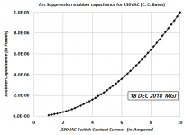
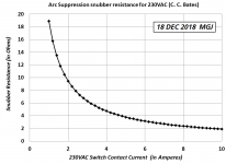
Here are the calculated values of arc suppressing snubber R and C, using the famous C. C. Bates equations mentioned in the links of post #11. Typically I use component values larger than these, but then I prefer to handle mains switching very gingerly.
_
_
Attachments
Why even use mechanical relays. Ahh ,, my low RDSon grow light Mosfets just
switched on for the 10k (th) time. Ohh , my amps inrush MOV just allowed (the
inrush before it got connected through A 5 milliohm MOSFET.
Oh no , that was my last amp. No inrush , 20A X 2 -60V at <1KG with my DIYA SMPS.
I would "wipe the floor " with any primitive analog PS. MY smps would turn crappy CFA PSRR into smart smps better than the best VFA.
I can also go class AB +G/H and eakk a 250W amp out of 2 pair BJT at 80+ (amp +PS)
efficiency .
Screwdrivers will never be molten , "magic smoke" will never happen and I
will look back at "monkey tek" and wonder why it did not become enhanced
in the 80's.
OS
Ohh , my amps inrush MOV just allowed
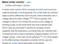
I don't think you mean "inrush MOV", I suspect that is a typo error.
The electronics industry uses the acronym MOV to denote a Metal Oxide Varistor, which is an overvoltage clamping device used to protect sensitive equipment against overvoltage surges on the AC mains. Attached below is the first paragraph of Wikipedia's explanation of MOVs. It appears in section 4.1 of their article named Surge Protector
_
_
Attachments
- Status
- Not open for further replies.
- Home
- Amplifiers
- Solid State
- Snubbing Relay Contacts - A Warning