
Just out of the interest you mentioned the 74HCT. Would this have any performance increase or safety parameters? If so how would that chip be implemented? I understand if I have exghausted your brain lol
Many many moons ago I built a preamp that used three 4017 chips in a discrete logic momentary pushbutton input selector and selectable twin tape record output feeds. For some reason one of the three (always the same one) would fail every few months. I added a Zener across the rail for transient protection and although I can't remember the details now I probably also added a 10uF or similar across the chip supply pins directly. It never failed again.
Just out of the interest you mentioned the 74HCT. Would this have any performance increase or safety parameters?
Not that I know of.
If so how would that chip be implemented? I understand if I have exghausted your brain lol
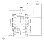
Also with a decoupling capacitor each. The inputs are internally protected, so you could tie pins 9 and 15 high by connecting them straight to the +5 V, without any resistor.
Inputs A...H would have to be connected to ground or +5 V, or some to ground and others to +5 V, whatever is convenient. It doesn't matter which go to +5 V and which to ground, but they should not be left unconnected.
You would gain some drive capabilities, the 74HTC can deliver and sink more current. Other than that I don't see anything special.Just out of the interest you mentioned the 74HCT. Would this have any performance increase or safety parameters? If so how would that chip be implemented? I understand if I have exghausted your brain lol
The 74HCT also has a larger output voltage swing, but I doubt that that would be an advantage.
Apparently everything can work well with 74LS, and with the larger voltage swings and current peaks of 74HCT, it would either work the same or have more problems with capacitive and inductive crosstalk from the shift registers to the other circuitry. At least that would be my best guess.
Apparently everything can work well with 74LS, and with the larger voltage swings and current peaks of 74HCT, it would either work the same or have more problems with capacitive and inductive crosstalk from the shift registers to the other circuitry. At least that would be my best guess.
I'm not sure if current is of concern here. The lines that go through it are I2s lines from the oversampling chip. 3 data lines I believe. I'm not an expert so please don't assume I am correct.
I maybe completetly wrong but I think I read somehwere that these chips actually reduce the peak voltage!?!?
Honestly I'm not even entirely sure what its purpose is, I just know that the CD2 is a very smooth sounding cd player and without these chips the sound is less smooth. And I do believe some people in the Ultimate DIY TDA dac thread have implemented a different version of this but its vastly complicated.
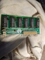
Thanks to you guys I do understand why it could have failed. I have found and attached my board from a while back when I did one. You can see it only has one single ceramic decoupling cap 10 or 100nf can't remember.
I maybe completetly wrong but I think I read somehwere that these chips actually reduce the peak voltage!?!?
Honestly I'm not even entirely sure what its purpose is, I just know that the CD2 is a very smooth sounding cd player and without these chips the sound is less smooth. And I do believe some people in the Ultimate DIY TDA dac thread have implemented a different version of this but its vastly complicated.
Thanks to you guys I do understand why it could have failed. I have found and attached my board from a while back when I did one. You can see it only has one single ceramic decoupling cap 10 or 100nf can't remember.
Attachments
- Home
- Source & Line
- Digital Line Level
- SN74LS166N shift chip why does it fail?