Hi,
I love the sound of my Sap-II pro (my first headphone amp) but it is just far too loud. Can anyone help me out on what resistors to change to adjust the gain?
Thanks 🙂
I love the sound of my Sap-II pro (my first headphone amp) but it is just far too loud. Can anyone help me out on what resistors to change to adjust the gain?
Thanks 🙂
Thanks, but its really the circuit diagram we need.
So I see an OPA2604 dual opamp. That should be easy to reconfigure the gain but without seeing a circuit and the configuration it is used in, together with component values its impossible to advise.
It might be easier for you to simply add an input attenuator.
So I see an OPA2604 dual opamp. That should be easy to reconfigure the gain but without seeing a circuit and the configuration it is used in, together with component values its impossible to advise.
It might be easier for you to simply add an input attenuator.
In this thread they suggested just changing the 30Kohm resistor...
http://www.diyaudio.com/forums/headphone-systems/275302-using-sapii-pro-tpa6120a2-lower-voltage.html
I have a multimeter can I maybe map out the circuit some how?
http://www.diyaudio.com/forums/headphone-systems/275302-using-sapii-pro-tpa6120a2-lower-voltage.html
I have a multimeter can I maybe map out the circuit some how?
I honestly don't know, at least not without having a unit in front of me and to figure the details out.
I see you have asked in the other thread.
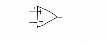
You should be able to get an idea of the circuit by drawing out the opamp and its components. You only need look at one channel, so that's say pins 1,2 and 3. Draw it out.
I see you have asked in the other thread.
You should be able to get an idea of the circuit by drawing out the opamp and its components. You only need look at one channel, so that's say pins 1,2 and 3. Draw it out.
I'm struggling a bit I can read which resistors are coming off each pin but after that I'm a bit stuck...
Thank you for your time btw 🙂
Thank you for your time btw 🙂
Last edited:
Not quite. I think you had the opamp pinout wrong. Looks like the signal comes in from the film coupling cap on the right via R20 (1k) and sees 30k (R19) from the noninverting input to ground. The remaining circuit is it's a noninverting amplifier with Rf = R17 = 30k from output to inverting input and Rg = R18 = 10k from inverting input to ground (values are a bit high for my taste, btw, those would contribute about as much noise as the opamp itself).
BTW, it's a good thing the OPA2604 is socketed, on +/-12 V it generally is not a particularly good performer save for RF immunity.
Assuming my reading of things is correct, you could put in like 1k for R17 for near unity gain. For the opamp, something not too fast and generally well-behaved would be advisable. I might try a lowly NJM4560, 4565, 4580, or 4556A. Less sure about the FET input side of things, maybe AD712? AD8620s are also nice but would require an adaptor board.
Sorry, I must have missed your earlier reply.
Its pretty much as sgrossklass has said really although I am a real fan of the OPA2604 🙂 its a great opamp for audio.
Another option based on sgrosslass's observations... you could also raise the 1k input resistor. Doing so would reduce the applied signal as the 1k and 30k form a divider.
Its pretty much as sgrossklass has said really although I am a real fan of the OPA2604 🙂 its a great opamp for audio.
Another option based on sgrosslass's observations... you could also raise the 1k input resistor. Doing so would reduce the applied signal as the 1k and 30k form a divider.
Sorry, I must have missed your earlier reply.
Its pretty much as sgrossklass has said really although I am a real fan of the OPA2604 🙂 its a great opamp for audio.
Another option based on sgrosslass's observations... you could also raise the 1k input resistor. Doing so would reduce the applied signal as the 1k and 30k form a divider.
Cool thanks to you both. What is the formula for the gain? Gain = R1/R2?
Using the references from sgrossklass th gain is (R17/R18) + 1
So that works out to a gain of 4. The input attenuator as it stands (the 1k series feed, 30k to ground) has negligible effect.
You could just link R17 out as a trial. The OPA2604 is 'unity gain stable' and so it should be fine.
So that works out to a gain of 4. The input attenuator as it stands (the 1k series feed, 30k to ground) has negligible effect.
You could just link R17 out as a trial. The OPA2604 is 'unity gain stable' and so it should be fine.
Using the references from sgrossklass th gain is (R17/R18) + 1
So that works out to a gain of 4. The input attenuator as it stands (the 1k series feed, 30k to ground) has negligible effect.
You could just link R17 out as a trial. The OPA2604 is 'unity gain stable' and so it should be fine.
R17 is 8K and R18 is 7.5k
So Gain = R17/R18 = 8/7.5 + 1 = 2.06*....
???
So I've tried reducing the 30k (R19) to 5k... little to no change. Put it back to 30. Then changed the 1k (R20) to 15k... again no noticeable change.
So sorry I didn't read your post. The 1k and 30k are the input attenuator? That's why changing them made little difference?
So R17/R18 are the gain they are only at 8k and 7.5k... What should I change them to?
So R17/R18 are the gain they are only at 8k and 7.5k... What should I change them to?
8k and 7.5k are funny values.
Is that how they are marked or is that what you measure ?
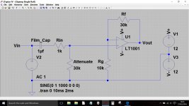
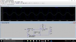
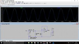
This seems to be the configuration you are describing which has a gain of four. The input voltage as shown is 1 volt peak to peak. If you look at the following images you can see the effect of the component changes on the gain.
Personally I suspect simply altering the input attenuator could be the way to get the best overall result. Noise isn't really an issue here and there can be sonic benefits to running an opamp with gain rather than with 100% feedback.
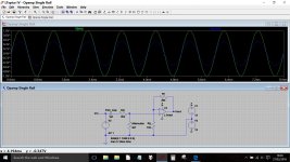


They were the measured values, they are all marked as 10k. So I tried just closing the Rf connection with a small bit of wire and it's allowed me to get the volume to 9 o'clock before I could barely get to 7... Is it OK to run it without a resistor there? Would I be better off adjusting the Rg as well?
This makes no sense if Rf is R17.... I'm confused now. Must have 17 and 18 the wrong way round
This makes no sense if Rf is R17.... I'm confused now. Must have 17 and 18 the wrong way round
Last edited:
Measuring resistors in circuit doesn't work because you get to read all the other stuff in parallel with them as well.
Rf is the one that connects the output of the opamp to the - input. If you short that resistor out so that it becomes zero ohms... and that's not the same as no ohms. No ohms means it is removed and we mustn't do that. Shorting it allows the opamp to function with a gain of unity (gain of 1).
Quick test you have the correct resistor... just short pins 1 and 2 (for one channel) and pins 7 and 6 (other channel) together.
If that is still to loud then we need to look at altering the input attenuator instead.
- Status
- Not open for further replies.
- Home
- Amplifiers
- Headphone Systems
- SMSL Sap II too loud

