smps help
Hi Dimonis
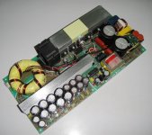
greetings need some help i am trying to make a half bridge smps 3kw
based on TL494 for a class d audio amplifier i have T63 round torridal core and
EE65 CORE smps working freqency is 70khz dc output rails are 90 0 90 dc +/-
i have managed to make the smps work need confirmation of primary turns and
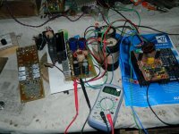
WIRE GAUGE to be used on T63 or EE65 CORE hoping you can help out picture of smps attached showing T63 CORE😕
warm regards
andrew lebon
Hi Dimonis
greetings need some help i am trying to make a half bridge smps 3kw
based on TL494 for a class d audio amplifier i have T63 round torridal core and
EE65 CORE smps working freqency is 70khz dc output rails are 90 0 90 dc +/-
i have managed to make the smps work need confirmation of primary turns and
WIRE GAUGE to be used on T63 or EE65 CORE hoping you can help out picture of smps attached showing T63 CORE😕
warm regards
andrew lebon
Attachments
What is the DC Input voltage? Around 325 VDC (only rectified and capacitor filtered line voltage of 230 VAC - what would be not so good for 3kW), or around 400 VDC from a PFC-pre-converter?
What topology for halfbridge exactly? Hard-switched or maybe series-resonant-converter (maybe with operation at resonant frequency and without feedback control, what would be relatively easy to implement, and would give excellent results for switching loss)?
Could you post schematic?
What topology for halfbridge exactly? Hard-switched or maybe series-resonant-converter (maybe with operation at resonant frequency and without feedback control, what would be relatively easy to implement, and would give excellent results for switching loss)?
Could you post schematic?
If dimonis doesn´t know the input voltage and exact topology (e.g. what possible duty cycle, what kind of secondary rectification? Center tapped/current doubler, diodes or sync-rec., or other?..., ...), he probably can´t give you hints for turn count and/or wire gauge/hf-litz version for optimal performance (not even to a certain degree).
If you think: "This guy is nuts, and doesn´t know, what i want..." --- I mentioned pfc and zvzcs srconverter only because i like power factor and soft-switching/efficency.
Anyway, i only tried to help.
If you think: "This guy is nuts, and doesn´t know, what i want..." --- I mentioned pfc and zvzcs srconverter only because i like power factor and soft-switching/efficency.
Anyway, i only tried to help.
Hi FQR
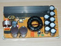
greetings its a simple half bridge smps cloned from the picture above i cloned it from
the pcb today theres no schematic given by detex audio i wound T63 CORE USING 20 TURN
for primary pfc is way above my head just trying to learn basics of smps
warm regards
andrew
greetings its a simple half bridge smps cloned from the picture above i cloned it from
the pcb today theres no schematic given by detex audio i wound T63 CORE USING 20 TURN
for primary pfc is way above my head just trying to learn basics of smps
warm regards
andrew
Hi FQR
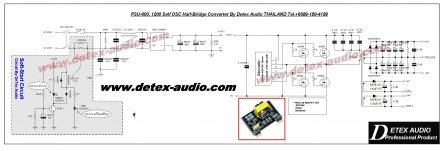
greetings this schematic is 1200 watts self osscilating the picture of smps posted is
TL494 with gdt high power version is with igbts i have the igbts 80 amps 600 volts but pcb has to be designed for igbt protection
warm regards
andrew
greetings this schematic is 1200 watts self osscilating the picture of smps posted is
TL494 with gdt high power version is with igbts i have the igbts 80 amps 600 volts but pcb has to be designed for igbt protection
warm regards
andrew
Uuuh, you mean, you made a supply as a copy from another, and you know nearly nothing about its function?
Maybe it´s a simple hard-switched PWM con. Look if there is(are) no resonant capacitor(s), and even more, no addittional inductor, in series between switched power nodes and transformer primary.
Maybe it´s a simple hard-switched PWM con. Look if there is(are) no resonant capacitor(s), and even more, no addittional inductor, in series between switched power nodes and transformer primary.
Sorry, was too late.
80-amps-IGBTs? Wow. Do you already have this protection circuit?
Probably it´s a simple hard-switched PWM conv. If I were you, I would take the EE65, with this core you can easily try different winding counts, till you are happy. I can give you examples to try.
But further quests: What secondary? Two diodes or bridge? And if you are obligatorily willing to try the toroid, then one has to know the Count of secondary, to give you hints for Primary.
I should read more accurate. You made it with 20 turns at primary? Then, why you asked dimonis for primary turn count? Or did you mean secondary? Confused...
The schematic i posted is a resonant one. Not really good, but kind of resonant.
You already made some switching supplies. I think, we talked past each other, probably you know much more, than i thought.
And sorry, my web Connection fluctuates, so my answers are often for your last post, because i can´t load the actual, the new one, at the right time... :-(
If the primary is 20 turns, then you would need 2 x 12 turns at secondary for bridge rectifier giving 90+, ground, 90-. Because the halfbridge switches one side of the primary between V+ and V-/ground, but the other side is fixed at half this voltage. So input voltage of 325V is halved effectively.
Is this video from you? It´s a shame, my computer sound system is not very good. However, the pulsating current looks nice...
Last edited:
my smps is off center tap using ee55 ferrite core, and am using sg3525 at 47khz, power transistor irf3205 ultra fast diode is rhrp1560. i used gauge 22 for the secondard 1 wire in hand 74 turns while for the primary still gauge 22 16 wires in hand 2+2 turns, my ee55 ferrite core has no air gap, output capacitor 100uf 400v. if i load the dc-dc converter output the mosfet get very very hot. please i need your help to stop the heating thanks.
You forgot to mention the most important data: primary current and voltage, but i guess it is for car battery, 12 V nominal, and about 50 A.
In center tapped push-pull topology the most important source of loss is primary-to-primary leakage inductance. When you switch off MOSFET1, then some of the flux (Iprimary*Lp1p2leakage) can be relaxed only through MOSFET1, creating a voltage enough to open Zds (Avalanche diode inside the MOSFET). Power loss is somewhat more then Ip^2*Lleakage*fsw. Lleakage is tipically 20-100 nH in a good design, so for example 50A*50A*50nH*50kHz=6W is acceptable, but if you don't optimise layout and transformer winding, you can reach 500 nH, which means more than 60W loss at 50A.
But there are many other possibilities to ruin efficiency. For example: input choke. Give a chance to find it by posting details about your design! 1st: actual schematic (not basic design, but the really built circuit!). 2nd: results of measurements (minimum: input voltage and current). 3rd: photos.
General rule: the error is always where you don't search for.
In case, SMPS was designed and crafted correct way. But due to one of, or even several, reasons below, this is not our case :In center tapped push-pull topology the most important source of loss is primary-to-primary leakage inductance.
and am using sg3525
output choke not even mentioned, and probably, just as usually, there is no RC snubbers...the primary still gauge 22 16 wires in hand 2+2 turns,
The source of problem here looks to be a Flux Walking. In some moments core going in to saturation, and simply disappearing from the circuit, leaving MOSFETS to load just an DC resistance of primary winding.
It is very difficult to make 2 equal windings, almost impossible to create an equal windings just from 2 turns of wire, on toroid core especially, AND ABSOLUTLEY IMPOSSIBLE TO CONTROL such transformer, by an IC, that don't have PULSE BY PULSE CURRENT CONTROL.
To deal with the leakage inductance - correct RC networks should be used on primary side, to reduce these ugly glitches .
The good output inductor should to decouple MOSFETS and rectifiers from output capacitor. It required to reduce current stress due to charging Cout.
AND ABSOLUTLEY IMPOSSIBLE TO CONTROL such transformer, by an IC, that don't have PULSE BY PULSE CURRENT CONTROL.
Don't shout! Such impossible things happen every day. I also made center tapped push-pull SMPS with 3+3 turns and TL494. (And also made it with UCC2808, but it doesn't solve the problem of asymmetry.) Symmetry is important indeed, but can be achieved.
RC snubber doesn't reduce power loss, actually increases it.
The source of problem here looks to be a Flux Walking.
Neither of us has any information yet about what's going on there in reality.
The good output inductor should to decouple MOSFETS and rectifiers from output capacitor. It required to reduce current stress due to charging Cout.
No output inductor is good enough to limit inrush current. It must be implemented differently. But primary to secondary leakage inductance can limit the current.
BTW: asymmetry is always in the leakage inductance.
PS: Who said toroid?
Last edited:
Tolyan !AND ABSOLUTLEY IMPOSSIBLE TO CONTROL such transformer, by an IC, that don't have PULSE BY PULSE CURRENT CONTROL.
Current control is needed mostly in feedback systems with regulated outputs. To avoid saturation of the core you only need to make the flux a little lower of max.
If you want to use the core at max possible flux , the V*sec regulation may help . It can be easily achived with the 3825 controller .
Where ? Inside of commercial products ? - I'll trust. But those toys are just an example how not to build an good SMPS. Good examples how to build - SMPS designed for the military aerospace, or navy. In practice, I personally know one guy, that designing such SMPS, and he is my teacher for that subject.Such impossible things happen every day.
From other side it is good that TL494 based push pull and similar "miracles" exists: time to time, I can to earn $$ for repair of some car amp.
But it is simple to imagine, that initial tests performed at room temperature, and either heat sink used. It should to be good source of energy to bring the low impedance MOSFETS to overheating. The primary candidate - core saturation, and while it brings an SMPS to catastrophic failures, it should to be checked and eliminated firstly.Neither of us has any information yet about what's going on there in reality.
Without pulse by pulse current limiting ? You tell me how ! Cap in series with the primary (for 50A) not in count ;-)Symmetry is important indeed, but can be achieved.
So what is it purpose for push pull ? Just to filter EMI/RFI ?No output inductor is good enough to limit inrush current.
Where ? Inside of commercial products ? - I'll trust.
From "ABSOLUTLEY IMPOSSIBLE TO CONTROL" we reached to mass production. 🙂
But those toys are just an example how not to build an good SMPS. Good examples how to build - SMPS designed for the military aerospace, or navy.
Big words without meaning and relevance.
In practice, I personally know one guy,
Personal arguments don't work here.
Whos signature is this? 🙂that designing such SMPS, and he is my teacher for that subject.
"Those who can, do. Those who can't, teach..."
From other side it is good that TL494 based push pull and similar "miracles" exists: time to time, I can to earn $$ for repair of some car amp.
Relevance I miss. But Offtopic either way.
But it is simple to imagine, that initial tests performed at room temperature, and either heat sink used. It should to be good source of energy to bring the low impedance MOSFETS to overheating. The primary candidate - core saturation, and while it brings an SMPS to catastrophic failures, it should to be checked and eliminated firstly.
Well, must be checked indeed. But not the only source of power loss, and not unavoidable.
Without pulse by pulse current limiting ? You tell me how ! Cap in series with the primary (for 50A) not in count ;-)
In center-tapped push-pull, serial cap is otu of question. No need any special trick. It works as is. Some symmetry, and some intrinsic relaxation mechanisms, I don't have time to discuss.
So what is it purpose for push pull ? Just to filter EMI/RFI ?
"Purpose"? It's a mental phenomenon. In a particular design ask the designer! Can be good for reducing peak/average secondary current, or reduce the ripple on output capacitor, or to achieve a slow response to build an average current controller using slow current sensor (with hall-sensor), or to achieve very low output current without too narrow pulses, etc... But 1 thing is sure: you can't use it (alone) to limit output capacitor charging speed.
+1 thing: output choke can prevent 1 of the flux relaxation mechanism.
I don't want to distract this topic.
I have calculate the transformer with Exceleent IT but the windings give a lot more voltages in the simulation with the outcome, like for 300 volts I did get 11 mH 73 windings. it gave with 100 Khz switching 860 volts.
I have a pc smps transformer used, not nown specs but did try more then one all gave wroungb stuff, I have als 7300 version.
I have 15 volts 10 amps, 2x120 volts 250 mA and 300 volts 100 mA for tubes/hybrid supply.
regards
I have a pc smps transformer used, not nown specs but did try more then one all gave wroungb stuff, I have als 7300 version.
I have 15 volts 10 amps, 2x120 volts 250 mA and 300 volts 100 mA for tubes/hybrid supply.
regards
Attachments

- Status
- Not open for further replies.
- Home
- Amplifiers
- Power Supplies
- SMPS transformer design tool (ver.4000)