Here it is and I wonder if winging fill factor has something to do with it
I think ,no , it's because of too small turns of the secondary , discreet 1 or 2 , you cannot wind 1,5 turns 🙂
If you choose non regulated output - every thing would be OK 😉
Attachments
Not exactly the secondary , i'd say ,the duty cycle which the transformer can provide with such turns.so secondary is limiting the power, because of one less turn?
ok, i understand, thank you!Not exactly the secondary , i'd say ,the duty cycle which the transformer can provide with such turns.
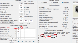
Here's a full and complex design tool for calculating the SMPS transformer based on a push-pull , half-bridge and full-bridge topology .
It has many pop-up tips to help you to use it and correctly paste the values.
I think that it'll be very useful for many of you , as for the beginners and so as for the guru of DIY.
Enjoy it !.

Hello sir,
if you have inductor computation, please post it for me, thanks so much🙂🙂
my is nichole am new in smps, my mosfet get very hot if loaded i don't no why, am using ee55 ferrite core.
Hello,
can you please describe your SMPS exactly? With this little information, sorry, probably nobody knows what you may mean.
Cheerio...
can you please describe your SMPS exactly? With this little information, sorry, probably nobody knows what you may mean.
Cheerio...
my smps is off center tap using ee55 ferrite core, and am using sg3525 at 47khz, power transistor irf3205 ultra fast diode is rhrp1560. i used gauge 22 for the secondard 1 wire in hand 74 turns while for the primary still gauge 22 16 wires in hand 2+2 turns, my ee55 ferrite core has no air gap, output capacitor 100uf 400v. if i load the dc-dc converter output the mosfet get very very hot. please i need your help to stop the heating thanks.
oguzie
What is the leakage inductance? Do you measured?
And do you have some screenshots? I'm interested to see G-S voltage and D-S voltage for the power MOSFET's.
What is the leakage inductance? Do you measured?
And do you have some screenshots? I'm interested to see G-S voltage and D-S voltage for the power MOSFET's.
oguzie
1. It's good idea to avoid 2 turns winding...
2. No one eill be able to determinate your problem without information about :
a. primary supply voltage
b. core material (exectly mark of ferrite)
c. It's good idea to post schematic of your smps
d. It's good idea to post screenshots from you scope
are your core same dimentions like this one - http://www.ferroxcube.com/prod/assets/e552821.pdf ?
Do you used output inductor with fine MPP or at least iron powder core ?
called push-pull topology.my smps is off center tap
Generally there are 2 kinds of looses, that brings mosfet's to overheating. Looses related Ciss charging by control cirquit, and looses related to Rds/on. Ciss is not your case, because 47K is relative low frequency. The next are looses on open d/s channel. These dependent on current trough mosfet. Now that current can just DRAMATICALY rice in case, if core diven in to saturation. Saturated core just disappearing from you transformer, and mosfets are loadel to primary winding passive resistance. Reasons for core saturation are 2 : 1 magnetic flux exeeds limits for core used due to wrong designed transformer, 2 magnetic flux exeeds limits for core used due to fenomenon known like "flux walking"
P.S how much watt drains load from you SMPS ?
P.S how much watt drains load from you SMPS ?
Hello , fellows.
I think this thread is about the design tool for calculating SMPS transformers? So I suggest not to discuss you private SMPS that you build . Thank you!
PS And as a advertisement - more design tools , for calculating inductors , flyback , on ferrite cores and metall powder core , etc.
Right from the author !
diysmps
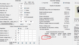
This is a nice tool.
Can someone explain the three rectification options? I'm almost sure I need to choose bridge but my circuit is a single rail with a center. 😕
It's also saying I need a 2968uh choke. That's a little big.
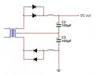
Circuit is attached.
Can someone explain the three rectification options? I'm almost sure I need to choose bridge but my circuit is a single rail with a center. 😕
It's also saying I need a 2968uh choke. That's a little big.
Circuit is attached.
Attachments
Last edited:
- Status
- Not open for further replies.
- Home
- Amplifiers
- Power Supplies
- SMPS transformer design tool (ver.4000)