hi guys
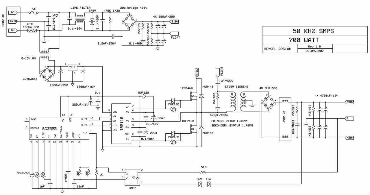
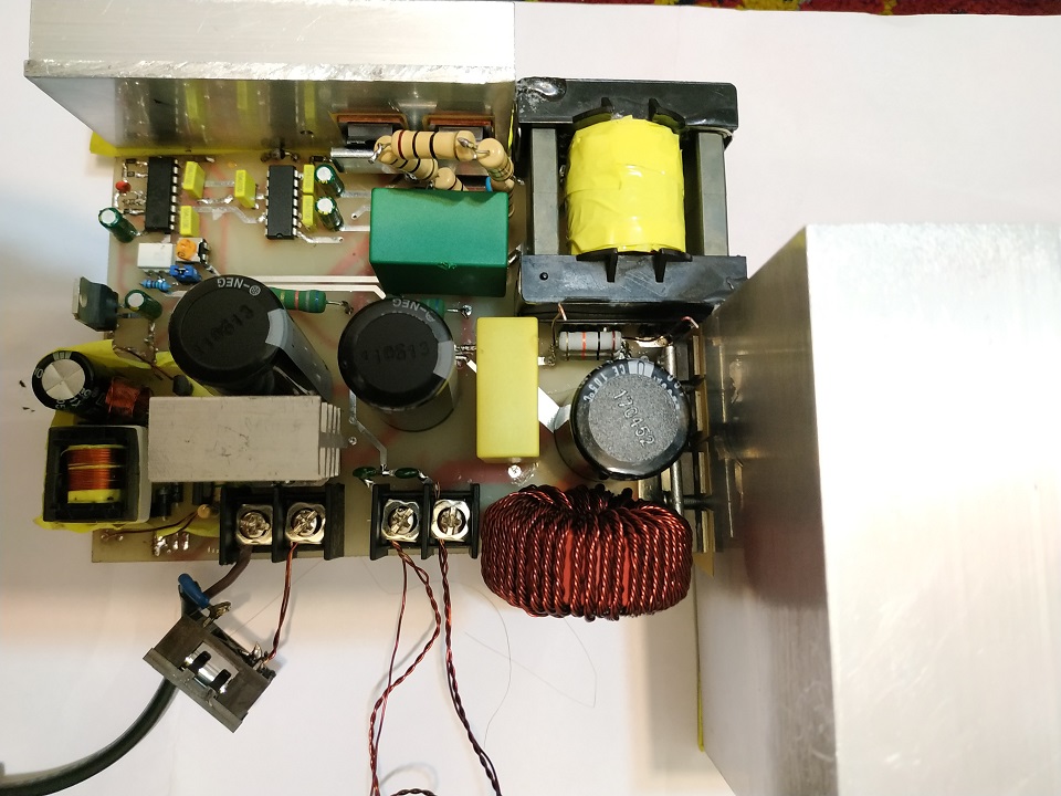
i use this schematic(VEYSEL ARSLAN Half bridge) and build my smps.output is single instead of double at 36V and output current is 20A.freq is 100KHz/core is etd44/primary turns is 13(6*0.55mm litz)/secondary is 4 turn(21*0.55mm litz)
my problem is extereme temperature in 2 points:
1-at primary side 47ohm resistor become exteremly hot at 20A output just after 1 minute.i replace it with 7 6.8ohm 3watt resistor in series and each of them became very hot.why and what should i do?
2-under full load secondary winding become hot after 1 minute.in this case what should i do?
Last edited:
This is only a snubber. At first instance, I suggest to increase to WW to 1KV in place of actual 400V. Also, you can try a smaller cap value.
Winding temp may be almost certainly, a poor design: too many looses (Take into account Eddy and proxi looses). Did you use the Dowell curves when designing the trafo?
Winding temp may be almost certainly, a poor design: too many looses (Take into account Eddy and proxi looses). Did you use the Dowell curves when designing the trafo?
This is only a snubber. At first instance, I suggest to increase to WW to 1KV in place of actual 400V. Also, you can try a smaller cap value.
Winding temp may be almost certainly, a poor design: too many looses (Take into account Eddy and proxi looses). Did you use the Dowell curves when designing the trafo?
is 47PF/1KV instead of 150pf/400V good?(can i remove snubber?what happend?)
no i didn't use dowell curves!now what should i do?
Try 47pF. This network stops the rise and fall oscillations due to resonance between leakage inductance of the trafo and parasitic capacitances. Is oscillations are low level, you can get rid of this net. Check with a large BW oscilloscope.
i didn't have oscilloscope and just can test various values to find best choice!Try 47pF. This network stops the rise and fall oscillations due to resonance between leakage inductance of the trafo and parasitic capacitances. Is oscillations are low level, you can get rid of this net. Check with a large BW oscilloscope.
can i increase resistor value?
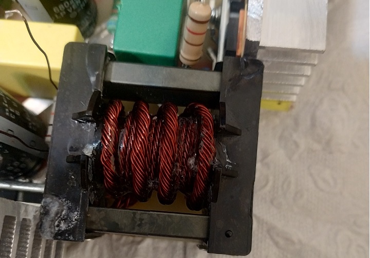
my trafo has 13 turns primary in 1 layers and 4 turn secondary top over primary.i can control secondary temp by cooling fan but snubber resistor is still problem
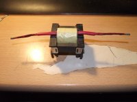
my Trafo:
Last edited:
The trafo looks good, but it will be better interlaying secondary and primary, as ½pri, 1 sec, ½pri. Take a reading to the Lloyd Dixon's articles at TI.com
you mean for example in first layer i wind 3 turn primary and 1 tun secondary and again 3 turn primary and 1 turn secondary and continue this way ?The trafo looks good, but it will be better interlaying secondary and primary, as ½pri, 1 sec, ½pri. Take a reading to the Lloyd Dixon's articles at TI.com
about Dixon's articles you mean those articles about winding losses?(skin-proximity)
The trafo does not look good. It is an abortion that is waiting to kill you.
You are dealing with an off line convertor and for your own safety or at least those you care about you need to implement proper primary to secondary isolation. That means at least 3mm margins using margin tape either side of the bobbin and at least three layers of insulating tape between primary to secondary. I know it might be hard to get hold of this stuff but it should be available from the catalogue you buy your bits from.
https://www.tdk-electronics.tdk.com/inf/80/db/fer/etd_44_22_15.pdf
The numbers appear to work out in terms of flux density excursion but as is often the case in a half bridge too low number of turns means you have to get creative with how you implement things. It may be counter-intuitive but sometimes more turns are better if the end solution is neater.
The following might fit.
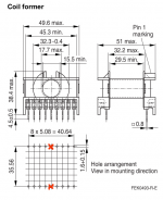
Your winding width is 29.5mm. Take away 3mm margins either side. You are left with 23.5mm. Use 16 turns primary with 5 turns secondary. Wind the primary as two sections/layers sandwiching the secondary. Don't forget the isolating tape and try to be neat.
First section/layer two ropes of 6 by AWG 26, heavy insulation. Wind side by side as one layer of 8 turns with 3mm margins. Leave tails.
Three layers full width insulating tape.
Second section/layer two ropes of 6 by AWG 22, heavy insulation. Wind side by side as one layer of 5 turns with 3mm margins. Leave tails.
Three layers full width insulating tape.
Third section/layer two ropes of 6 by AWG 26, heavy insulation. Wind side by side as one layer of 8 turns with 3mm margins. Leave tails.
Three layers full width insulating tape.
With the tails parallel each section. You can do this because the windings are in the same layer. Then connect the primaries externally in series.
In terms of winding width things may be fiddly but overall height is about 5mm and you have just over 7mm.
As suggested losses are down to penetration/skin depth. proximity and layer factors. Splitting the primary around the secondary leaves the primary as, two, one layer items but the secondary becomes a half layer.
In terms of layers one of the important factors is overall height of the layer. Using a big fat litz wire/rope ends up with high height. Splitting to two or more windings in the same layer reduces that height but in order to parallel them they must be in the same layer.
That's similar to the twist in a rope. The twist ensures that the wires that are paralleled in the rope are subject to the same integral or overall flux and don't end up shorting any residual or minimise such effects.
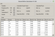
The zip file is a program written in Delphi 4 that does the sums based on Dowell's paper. Should still run under Windows and runs under Wine in Linux.
Try not to kill yourself.
You are dealing with an off line convertor and for your own safety or at least those you care about you need to implement proper primary to secondary isolation. That means at least 3mm margins using margin tape either side of the bobbin and at least three layers of insulating tape between primary to secondary. I know it might be hard to get hold of this stuff but it should be available from the catalogue you buy your bits from.
https://www.tdk-electronics.tdk.com/inf/80/db/fer/etd_44_22_15.pdf
The numbers appear to work out in terms of flux density excursion but as is often the case in a half bridge too low number of turns means you have to get creative with how you implement things. It may be counter-intuitive but sometimes more turns are better if the end solution is neater.
The following might fit.
Your winding width is 29.5mm. Take away 3mm margins either side. You are left with 23.5mm. Use 16 turns primary with 5 turns secondary. Wind the primary as two sections/layers sandwiching the secondary. Don't forget the isolating tape and try to be neat.
First section/layer two ropes of 6 by AWG 26, heavy insulation. Wind side by side as one layer of 8 turns with 3mm margins. Leave tails.
Three layers full width insulating tape.
Second section/layer two ropes of 6 by AWG 22, heavy insulation. Wind side by side as one layer of 5 turns with 3mm margins. Leave tails.
Three layers full width insulating tape.
Third section/layer two ropes of 6 by AWG 26, heavy insulation. Wind side by side as one layer of 8 turns with 3mm margins. Leave tails.
Three layers full width insulating tape.
With the tails parallel each section. You can do this because the windings are in the same layer. Then connect the primaries externally in series.
In terms of winding width things may be fiddly but overall height is about 5mm and you have just over 7mm.
As suggested losses are down to penetration/skin depth. proximity and layer factors. Splitting the primary around the secondary leaves the primary as, two, one layer items but the secondary becomes a half layer.
In terms of layers one of the important factors is overall height of the layer. Using a big fat litz wire/rope ends up with high height. Splitting to two or more windings in the same layer reduces that height but in order to parallel them they must be in the same layer.
That's similar to the twist in a rope. The twist ensures that the wires that are paralleled in the rope are subject to the same integral or overall flux and don't end up shorting any residual or minimise such effects.
The zip file is a program written in Delphi 4 that does the sums based on Dowell's paper. Should still run under Windows and runs under Wine in Linux.
Try not to kill yourself.
Attachments
Last edited:
The trafo does not look good. It is an abortion that is waiting to kill you.
You are dealing with an off line convertor and for your own safety or at least those you care about you need to implement proper primary to secondary isolation. That means at least 3mm margins using margin tape either side of the bobbin and at least three layers of insulating tape between primary to secondary. I know it might be hard to get hold of this stuff but it should be available from the catalogue you buy your bits from.
https://www.tdk-electronics.tdk.com/inf/80/db/fer/etd_44_22_15.pdf
The numbers appear to work out in terms of flux density excursion but as is often the case in a half bridge too low number of turns means you have to get creative with how you implement things. It may be counter-intuitive but sometimes more turns are better if the end solution is neater.
The following might fit.
Your winding width is 29.5mm. Take away 3mm margins either side. You are left with 23.5mm. Use 16 turns primary with 5 turns secondary. Wind the primary as two sections/layers sandwiching the secondary. Don't forget the isolating tape and try to be neat.
First section/layer two ropes of 6 by AWG 26, heavy insulation. Wind side by side as one layer of 8 turns with 3mm margins. Leave tails.
Three layers full width insulating tape.
Second section/layer two ropes of 6 by AWG 22, heavy insulation. Wind side by side as one layer of 5 turns with 3mm margins. Leave tails.
Three layers full width insulating tape.
Third section/layer two ropes of 6 by AWG 26, heavy insulation. Wind side by side as one layer of 8 turns with 3mm margins. Leave tails.
Three layers full width insulating tape.
With the tails parallel each section. You can do this because the windings are in the same layer. Then connect the primaries externally in series.
In terms of winding width things may be fiddly but overall height is about 5mm and you have just over 7mm.
As suggested losses are down to penetration/skin depth. proximity and layer factors. Splitting the primary around the secondary leaves the primary as, two, one layer items but the secondary becomes a half layer.
In terms of layers one of the important factors is overall height of the layer. Using a big fat litz wire/rope ends up with high height. Splitting to two or more windings in the same layer reduces that height but in order to parallel them they must be in the same layer.
That's similar to the twist in a rope. The twist ensures that the wires that are paralleled in the rope are subject to the same integral or overall flux and don't end up shorting any residual or minimise such effects.
The zip file is a program written in Delphi 4 that does the sums based on Dowell's paper. Should still run under Windows and runs under Wine in Linux.
Try not to kill yourself.
thank you so much.
i rewind trafo according to your tips.
but what is benefits of this sandwich winding method?does it affect on reduce proximity effect?
if i use three-layer insolation tape beetwen layers does it make heat dissipation problem?or not?
and finally isn' it better to use copper sheet instead of two bundle at secondary side(middle layer)?
Last edited:
Morbid is right about the transformer construction. You have to use the proper materials in order to maintain safety. Along with proper clearances on the PCB, the transformer must provide mains isolation. Care must be taken when designing and building mains circuitry, especially 220/240 mains. The enamel on the wire is not sufficient isolation and I wish you could just use Scotch tape but you cannot.
  I use type 1350F-2 from 3M. High temperature, flame proof, and puncture proof.
For a bridge forward circuit the coupling between the primary and secondary is mostly between the windings and less the core. Although there is more insulation tape required, sandwiching the secondary(ies) between the primary provides better magnetic coupling to the secondary (top and bottom) of the winding and lowers leakage. Also try to make each layer even all the way across the winding window. You don't want to have wasted space between the primaries and secondary; the height issue Morbid expressed. Otherwise efficiency will be low, EMI is high, and the snubber resistor burns up.😱.
Choose an even number of primary turns so that it can be split equally and that the number of secondary turns is an integer and provides the desired loaded output voltage. Then use Faraday's formula to derive the frequency for an appropriate Bmax. 16:5 with Fsw about 85KHz may suffice. Or maybe you go with 20:6.
My first transformer for offline half bridge took me 3 tries to get it right. So, make the circuit so that the transformer can be easily removed and re-wound in case you don't get it right the first time. A scope will be very useful in measuring any ringing on the primary.
Just a point of note, the mains voltage here is lethal and so I assume you are using an isolated source such as a mains isolation transformer /w fuse to power the circuit while you are building and testing? Also a bulb tester is useful. 
The enamel on the wire is not sufficient isolation and I wish you could just use Scotch tape but you cannot. I use type 1350F-2 from 3M. High temperature, flame proof, and puncture proof.For a bridge forward circuit the coupling between the primary and secondary is mostly between the windings and less the core. Although there is more insulation tape required, sandwiching the secondary(ies) between the primary provides better magnetic coupling to the secondary (top and bottom) of the winding and lowers leakage. Also try to make each layer even all the way across the winding window. You don't want to have wasted space between the primaries and secondary; the height issue Morbid expressed. Otherwise efficiency will be low, EMI is high, and the snubber resistor burns up.😱.
Choose an even number of primary turns so that it can be split equally and that the number of secondary turns is an integer and provides the desired loaded output voltage. Then use Faraday's formula to derive the frequency for an appropriate Bmax. 16:5 with Fsw about 85KHz may suffice. Or maybe you go with 20:6.
My first transformer for offline half bridge took me 3 tries to get it right.
So, make the circuit so that the transformer can be easily removed and re-wound in case you don't get it right the first time. A scope will be very useful in measuring any ringing on the primary. Just a point of note, the mains voltage here is lethal and so I assume you are using an isolated source such as a mains isolation transformer /w fuse to power the circuit while you are building and testing?
Also a bulb tester is useful. Attachments

For better efficiency in the rectifying stage, if you use two secondaries in series, you can use only two rectifier diodes instead of four. 😉
Full Fat Lloyd Dixon...
https://www.ti.com/seclit/ml/slup132/slup132.pdf
Interleaving reduces the layer/proximity effect. Covered in the above.
The tape is mylar/polyester 2mill [thousandths of an inch thick] and does not add much to winding height. There is no real penalty in respect of power losses.
Yes you can use foil but sourcing it is hard and using, insulating and terminating it, it is tricky.
you mean center-tapped instead of full wave bridge rectifying?but diodes efficiency isn't problem now.For better efficiency in the rectifying stage, if you use two secondaries in series, you can use only two rectifier diodes instead of four. 😉
now there is two problem;snubber resistor extereme heat and trafo secondary heat that i want solve them first.
Full Fat Lloyd Dixon...
https://www.ti.com/seclit/ml/slup132/slup132.pdf
Interleaving reduces the layer/proximity effect. Covered in the above.
The tape is mylar/polyester 2mill [thousandths of an inch thick] and does not add much to winding height. There is no real penalty in respect of power losses.
Yes you can use foil but sourcing it is hard and using, insulating and terminating it, it is tricky.
i wind trafo again according to sandwich method and test smps again.
i use LCR meter to measure inductance and leakage inductance.are these measured value especially leakage inductane sign of winding quality?
Last edited:
Again, I still suggest Lloyd Dixon's articles previously to start a new trafo.
Four diodes increase the looses in the diode bridge. Two diodes option increases looses in the trafo. Balance yourself which of them do you prefer.
Four diodes increase the looses in the diode bridge. Two diodes option increases looses in the trafo. Balance yourself which of them do you prefer.
Referring back to...
https://www.tdk-electronics.tdk.com/inf/80/db/fer/etd_44_22_15.pdf
There are a range of values quoted for the specific inductance, Al, of ungapped cores which depend slightly on type of material. 3300-4400nH per root turn. Your primary inductance, secondary open circuit should be about 16^2 x (3850E-9) or 1mH. Bear in mind the +30/-20% tolerance on those numbers.
Leakage inductance, secondary shorted, should ideally be about 2% ore lower of this value. The measurement is referred to primary. Don't be alarmed if it is slightly worse. Leakage inductance will have an impact on design of your snubber and the power it has to dissipate.
It rings with primary side parasitic capacitance during power switch off time. That will largely be dominated by mosfet drain source capacitance in parallel.
You can extract an approximate number, Cds, as Cds = Coss - Crss from the data sheet.
http://www.vishay.com/docs/91237/91237.pdf
This is extremely variable with voltage across the device and does not take into account other sources of parasitic capacitance.
Otherwise you can measure it in circuit if you have an oscilloscope. Knowing Lleak the frequency of oscillation will be Fres =1/2PIroot(Lleak.Cstray). You know Lleak measure Fres and solve for Cstray. You pick a Csnub of 3 times Cstray and Rsnub is root(Lleak/Cstray)
Maximum power loss in Rsnub is 0.5Lleak.Ipeakpri^2 times the switching frequency. Your peak primary current is Convertor Power divided by half the Input DC bus voltage.
All of these sums are estimates. It might be more accurate to consider voltage stored in stray capacitance because some of the energy due to current in the leakage inductance might be recovered during reset on the primary side.
There are also considerations as to where the leakage inductance really is. You can design/wind your transformer to associate it with the primary or the secondary.
http://www.ti.com/lit/ml/slup105/slup105.pdf
If you force it to the secondary snubbing might become easier and/or incur lower losses. However tricks like that impact your winding losses due to proximity and layer effects so you are likely to lose more than you gain by interleaving.
In respect of the suggestion of using two secondaries and two diodes for secondary rectification you end up with a more complex transformer which may end up losing in transformer losses what you gain in diode losses. It is also much easier to heatsink diodes.
You might consider something called the current doubler rectifier which makes use of a single secondary winding and two output inductors, your circuit suggests that there are two inductors already being used.
https://www.ti.com/lit/an/slua121/slua121.pdf
first thank you all especially MorbidFractal
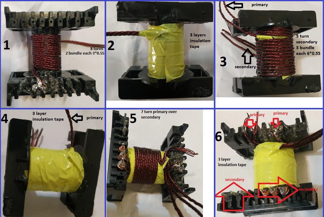
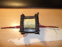
i wind trafo again as you see in picture.
reduce freq to 80 KHz.
now trafo temp especially secondary temp is less and at full load it's under 70 degree.
now snubber resistor temp is under 80 degree
finally smps can run continuously under full load(36V/21A/750WATT) with above temperature and with a fan that temps become very lower.
but about trafo is that looks good and safe now?can i wind it better?what advice?
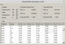
Looking neater. Your chosen 3 and 6 bundles appear to make more sense and get the job done. You might check losses using the calculator but if it is running at an acceptable temperature then...
It looks like you would achieve the margins on the primary but the secondary could be tight. Nice yellow tape. In part the remaining problem would be stabilising the margins. At the moment the problem is likely to be dressing of the wires as they exit the bobbin. It looks like your bobbin has a few war stories to tell.
Again this is down to isolation concerns and the obvious choice is to terminate primary and secondary windings on opposite sides of the transformer. My fault for not suggesting this previously.
Oh as an add. You should sleeve the windings as they exit to maintain the integrity of the isolation.
If you chop out the centre pin each side of the transformer then you end up with 10mm creepage and clearance, agency is 6mm, distance primary to secondary. Unfortunately that might not agree with your PCB.
However rather than having to wind from and return to one side of the transformer now, for example with the primary, you wind/terminate from one side the first primary section and terminate the opposite side. Then when you get to the second primary section you wind/terminate from the opposite side, series connection, back to the first side.
Your secondary windings just go straight across. If you want to be adventurous then you could bring the secondary ropes out as flying windings using the two notches in the top of the bobbin.
Here's one I did earlier, ages ago, for a 400W two switch forward convertor. Similar to yours but ETD49. Two primaries sandwiching the secondary. Also has a primary auxiliary, four secondary auxiliaries, two earth screens and four inter-winding screens.
Attachments
Last edited:
i have a question.you said secondary become a half layer.i want to know what is half layer?i can't understand why it's half layer?why it isn't one layer between two layer primary?The trafo does not look good. It is an abortion that is waiting to kill you.
You are dealing with an off line convertor and for your own safety or at least those you care about you need to implement proper primary to secondary isolation. That means at least 3mm margins using margin tape either side of the bobbin and at least three layers of insulating tape between primary to secondary. I know it might be hard to get hold of this stuff but it should be available from the catalogue you buy your bits from.
https://www.tdk-electronics.tdk.com/inf/80/db/fer/etd_44_22_15.pdf
The numbers appear to work out in terms of flux density excursion but as is often the case in a half bridge too low number of turns means you have to get creative with how you implement things. It may be counter-intuitive but sometimes more turns are better if the end solution is neater.
The following might fit.
Your winding width is 29.5mm. Take away 3mm margins either side. You are left with 23.5mm. Use 16 turns primary with 5 turns secondary. Wind the primary as two sections/layers sandwiching the secondary. Don't forget the isolating tape and try to be neat.
First section/layer two ropes of 6 by AWG 26, heavy insulation. Wind side by side as one layer of 8 turns with 3mm margins. Leave tails.
Three layers full width insulating tape.
Second section/layer two ropes of 6 by AWG 22, heavy insulation. Wind side by side as one layer of 5 turns with 3mm margins. Leave tails.
Three layers full width insulating tape.
Third section/layer two ropes of 6 by AWG 26, heavy insulation. Wind side by side as one layer of 8 turns with 3mm margins. Leave tails.
Three layers full width insulating tape.
With the tails parallel each section. You can do this because the windings are in the same layer. Then connect the primaries externally in series.
In terms of winding width things may be fiddly but overall height is about 5mm and you have just over 7mm.
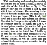
As suggested losses are down to penetration/skin depth. proximity and layer factors. Splitting the primary around the secondary leaves the primary as, two, one layer items but the secondary becomes a half layer.
In terms of layers one of the important factors is overall height of the layer. Using a big fat litz wire/rope ends up with high height. Splitting to two or more windings in the same layer reduces that height but in order to parallel them they must be in the same layer.
That's similar to the twist in a rope. The twist ensures that the wires that are paralleled in the rope are subject to the same integral or overall flux and don't end up shorting any residual or minimise such effects.
The zip file is a program written in Delphi 4 that does the sums based on Dowell's paper. Should still run under Windows and runs under Wine in Linux.
Try not to kill yourself.
i have a question.you said secondary become a half layer.i want to know what is half layer?i can't understand why it's half layer?why it isn't one layer between two layer primary?
Dixon does it better.
http://www.ti.com/lit/ml/slup197/slup197.pdf
It's down to how the MMF builds up as you traverse the windings. Non-interleaved you get a single peak in the middle. Interleaved you get two lower peaks, with a zero crossing.
Associated energy/loss is square of this.
A four layer primary split into two sections becomes two two layer sections. The cumulative MMF in each section, opposite each side, is halved.
A sandwiched four layer secondary straddles the zero point and behaves as two two layer sections.
A sandwiched three layer secondary straddles the zero point and behaves as two one and a half layer sections.
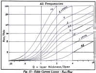
Using the graphs is a bit of a pain which is why I wrote the program. Using the program is also a bit of a pain because you still have to make intuitive choices and manipulate the results.
Note that it has an input for layers that includes half layers.
Attachments
Last edited:
Interleaving the windings reduces looses mainly from inductive effects, abut worses capacitive coupling, so you must balance between them.
A fact that is poorly known but that is very important, is to add a 4.7nF @ 1 or 2KV to close capacitive currents trough the trafo into the secondary circuit, and leave the to return to the primary. The absence of this condenser or too small capacitance conducts this RF currents into unwanted places, causing oscillations of the control circuitry, and lots of EMI, radiated and conducted. Also, the primary heatsinking for power devices MUST be refereed to to the primary low potential RF side (Called sometimes cold wire), say, or the positive bus or the negative one, by far the most common is the negative rail. This also permits the flow of RF currents from the tabs of the MOSFETs to ground to return pacifically to their origin: the primary side. NEVER ground those heatsinks, RF will circulate by the ground connection to unwanted places causing RF disturbation and lots of stupids problems (And headaches).
A fact that is poorly known but that is very important, is to add a 4.7nF @ 1 or 2KV to close capacitive currents trough the trafo into the secondary circuit, and leave the to return to the primary. The absence of this condenser or too small capacitance conducts this RF currents into unwanted places, causing oscillations of the control circuitry, and lots of EMI, radiated and conducted. Also, the primary heatsinking for power devices MUST be refereed to to the primary low potential RF side (Called sometimes cold wire), say, or the positive bus or the negative one, by far the most common is the negative rail. This also permits the flow of RF currents from the tabs of the MOSFETs to ground to return pacifically to their origin: the primary side. NEVER ground those heatsinks, RF will circulate by the ground connection to unwanted places causing RF disturbation and lots of stupids problems (And headaches).
- Home
- Amplifiers
- Power Supplies
- smps temp problem