Hello to all!
first thread in this forum 🙂 ..
I recently found a 100W 30V smps (from an old printer I guess) and i think of using it as the power supply for a small gainclone i m building (2x10watts with lm1875 at+-15V)
Using such a circuit would be ultra lo-fi ??? i think that its gonna work but i wouldnt like to end up with a noisy little amp..
My other option is a standard regulated psu..i already ave one 50VA toroid and i think that its enough for a 2X10 W gainclone, but most of the online projects use as big as it gets transformers wich i cant understand much why??? any help ??? 😀
Thanks and sorry if i have posted in the wrong place
Capacity wise it should be fine, your problem is going to be having to create a virtual earth which the speaker currents can return to. Stick with a traditional transformer supply if you are a beginner.
Thanks for the reply.
not a total begginer, i have an understanding in electronics, but i m sure i can learn from more experienced people (smtmz even from less 🙂 )
I mean using a topology like the one in the link to create the virtual ground, not exactly the same circuit.I think the transistors and the diodes wont be able to handle the current.
I find some other topologies for virtual ground on the net using opamps, but i have never again used high current opamps (except in gainclones in a way..)
In general, using a virtual ground to split a voltage supply would have noise or other unwanted effects ?
Any topology to suggest ?
Thanks!
p.s: this is a nice link explaining virtual ground circuts 🙂
I think the transistors and the diodes wont be able to handle the current.
The nice thing about this circuit is that they don't need to. The speaker will draw its current from the large capacitors, so make them large. The larger you make them the less voltage ripple you get at the virtual ground, and the more stable supply your amplifier "sees".
The transistor bridge only has the job to split the supply in two nice halves, and to keep that level. Keep in mind the current drawn from your circuit is pure AC.
Taking this to the top: when there would be such device as two capacitors without any leakage current and with identical capacity, you yould even completely omit that circuit. The two capacitors then would split the supply into two identical halves by themselves. Google for "capacitive divider", which is similar to a resistive divider but lossless and only for AC signals.
considering an AB class amp, in the first half of the cycle where the current is drawn from the positive supply rail (and returns through the virtual ground), shouldnt the transistor's CE current be capable to hold the same amount of current that the load demands ?
I think i ll go with a regulated psu, but i want to try out such a circuit..if i come up with a toasted transistor i ll post back here 🙂 if it works good i ll post again here 😛
Thanks!
Aris
I think i ll go with a regulated psu, but i want to try out such a circuit..if i come up with a toasted transistor i ll post back here 🙂 if it works good i ll post again here 😛
Thanks!
Aris
Using a bridged topology would eliminate the need for a large current return to a virtual GND or a DC blocking output cap. You can use a higher Z floating reference halfway between B+ and GND 0V as the input source common so the output of each amp will be halfway between the B+ and 0V. This is the best way to get 0VDC output from a single end power supply, especially with only 30V. 50Wrms @ 8R is possible from full bridge topology.
considering an AB class amp, in the first half of the cycle where the current is drawn from the positive supply rail (and returns through the virtual ground), shouldnt the transistor's CE current be capable to hold the same amount of current that the load demands ?
No. The current flows from the + terminal of the upper capacitor through the amp into the speaker + terminal, then back from the speaker - terminal into the - terminal of the same capacitor. Provided that this capacitor is large enough, this will result in a slightly reduced voltage across it. With the next negative swing of the amplifier, this repeats with the lower capacitor. With the next 50hz peak from the transformer/rectifier, both capacitors are recharged.
The important thing is that the current flowing through the speaker is pure AC, which means that both capacitors are ALWAYS discharged by the same rate over time.
Try this circuit, make sure that the transistors can withstand the full supply voltage plus margin (I mean from + to -, not from + to "virtual gnd"). Keep the balancing currents flowing through them small enough so they do not get overheated. You can even start with a transformer, a rectifier, two capacitors and two resistors across them. Works just as good.
What is important here is that the amp itself draws approximately the same idle current (no signal, speaker disconnected) from both supply rails into GND. You should measure this to be sure. The more imbalance you have the smaller the resistor value must be.
This is the best way to get 0VDC output from a single end power supply, especially with only 30V. 50Wrms @ 8R is possible from full bridge topology.
My proposal does not have 4 times output power as your has, but it does has advantages: simpler, cheaper. Just two resistors in the simplest case. And no turn-on pop as for the "standard" method of adding a capacitor in series to the speaker.
Hi!
i m posting here again so as not to start a new thread..
i m about to test a rail splitter like this one
i want to split a 30Volts into +-15 and i m not to sure what should the rating of the capacitors be...25volts would be ok ???
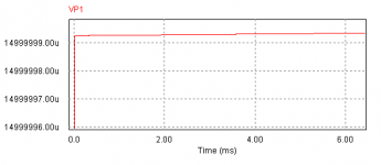
i run a quick n dirty simulation with psim of the divider with a resistive load showing that the voltage across each capacitor is from zero to nearly 15 volts...
so this is the schematic and the voltage across one capacitor.
also for 1,5 amperes at the positive rail (through the resistor from +15 v to ground) there is 1,5uAmperes at the emitter of the respective transistor
i m posting here again so as not to start a new thread..
i m about to test a rail splitter like this one
i want to split a 30Volts into +-15 and i m not to sure what should the rating of the capacitors be...25volts would be ok ???
i run a quick n dirty simulation with psim of the divider with a resistive load showing that the voltage across each capacitor is from zero to nearly 15 volts...
so this is the schematic and the voltage across one capacitor.
also for 1,5 amperes at the positive rail (through the resistor from +15 v to ground) there is 1,5uAmperes at the emitter of the respective transistor
Attachments

Hi!
i m posting here again so as not to start a new thread..
i m about to test a rail splitter like this one
i want to split a 30Volts into +-15 and i m not to sure what should the rating of the capacitors be...25volts would be ok ???
i run a quick n dirty simulation with psim of the divider with a resistive load showing that the voltage across each capacitor is from zero to nearly 15 volts...
so this is the schematic and the voltage across one capacitor.
also for 1,5 amperes at the positive rail (through the resistor from +15 v to ground) there is 1,5uAmperes at the emitter of the respective transistor
The component values in your circuit are not shown....
The capacitor must be rated for 30v plus margin, so a 35v type should be ok. You must account for an unbalanced bridge, for example if the load from gnd to - is shorted. In this case the capacitor from gnd to + sees the entire voltage from the rectifier. If you do not want to cover this situation then a +25v type should be ok.
Hi!
i m posting here again so as not to start a new thread..
i m about to test a rail splitter like this one
i want to split a 30Volts into +-15 and i m not to sure what should the rating of the capacitors be...25volts would be ok ???
i run a quick n dirty simulation with psim of the divider with a resistive load showing that the voltage across each capacitor is from zero to nearly 15 volts...
so this is the schematic and the voltage across one capacitor.
also for 1,5 amperes at the positive rail (through the resistor from +15 v to ground) there is 1,5uAmperes at the emitter of the respective transistor
Are the diodes as the bases LED's? If you use regular diodes, the circuit won't work.
the component values are the same as the ones in the link
wich means 5k for the base resistors, 2.2 ohm for the emiter resistor and the diodes are 1n4148.. also the capacitors that form the virtual ground(them not shown in the link) are 4700u
why you think it wont work??? i breadboarded it and tried it with no load connected and it was halving good enough the voltage...
and the capacitors why should they be 30 volts ? i mean since all the time the voltage across them is 15volts..or not ??
again thanks tatus for the help
the component values are the same as the ones in the link
You need to calculate all component values to your needs, just take over the principle:
- the emitter resistors (4.7 ohm) set the output impedance (beta * R3, beta * R4), it should be large enough so the transistors do not get overheated during continuous short of + to gnd or - to gnd. That 4.7 ohm or even 2.2 ohm will burn the transistors.
- C1/C2 should be chosen large enough so that their output ripple is kept low - the inital circuit totally oversizes them. Their output impedance at 20Hz is 8.4 ohms, which is not necessary to drive the base of a transistor
-R1, R2 must be able to supply the transistor's base current at maximum collector current, plus some margin (typically a factor of 2 to 5)
- C3, C4: as large as money can buy 🙂
It will work, but it will have very poor characteristics. The original circuit will operate in pure class B mode. If this is acceptable for your application, everything is fine. If you want nice regulation, class A will be needed. In this case you have to add more bias voltage to the transistors. This is often done by using an LED (1.5 v) instead of a diode (0.7 v).why you think it wont work???
Connect an AC load to the output and watch the voltages with an oscilloscope.i breadboarded it and tried it with no load connected and it was halving good enough the voltage...
I explained that in post 11. Just consider making a short between gnd and +. The result will be that the capacitor between gnd and - sees the full voltage from the supply.and the capacitors why should they be 30 volts ? i mean since all the time the voltage across them is 15volts..or not ??
again thanks tatus for the help
You're welcome!
- Status
- Not open for further replies.
- Home
- Amplifiers
- Power Supplies
- smps spilt supply