No i mean that for supply the SMPS i use a 220V=>14.5V and for the smps i use a pc transformer!!
Anyway what do u suggest as controller?
Anyway what do u suggest as controller?
I don't understand clearly! Expecially "impedance of the" etc etc... What mean?If you are using a car battery, the current draw may be limited by the impedance of the circuit connected to its terminals.
Is there a final schematic that shows all the changes used to make it work? Could someone post it?

My final schematic of SMPS!
An externally hosted image should be here but it was not working when we last tested it.
An externally hosted image should be here but it was not working when we last tested it.
Just for subwo1..
I've added the cooler for Rectifier's diode... Are them enough?
An externally hosted image should be here but it was not working when we last tested it.
I've added the cooler for Rectifier's diode... Are them enough?
They look big enough. If you have trouble, you can replace them with schottky diodes. You can get 5amp 100piv schottky diodes which are available in plastic barrel packages and which do not require heatsinks. But those heatsinks look like a good solution.
I am still wondering if there is a reason you don't want to use the error amp in the SG3524 to control the pulse duration. You might as well just use a multivibrator like a '555 in this application if not.
Subwo1...
What maybe the reason for which if i connect a real load (a power amp for example) the voltage goes quicly down? From +/-42V to 0.5-1V???
I don't think that's normal...
What maybe the reason for which if i connect a real load (a power amp for example) the voltage goes quicly down? From +/-42V to 0.5-1V???
I don't think that's normal...
Ok explain me how i should modify my schematic to make this! 🙂I am still wondering if there is a reason you don't want to use the error amp in the SG3524 to control the pulse duration. You might as well just use a multivibrator like a '555 in this application if not.
and perhaps you would like to use the current sense on the LM3524 next. At any rate, here's how to control the pulse width using the error amp.MaXiZ said:
Ok explain me how i should modify my schematic to make this! 🙂
voici:
Attachments
and what about this?
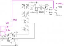
And 2.5V mean that i should regulate the trimer to have 2.5V ad pin1?
An externally hosted image should be here but it was not working when we last tested it.
And 2.5V mean that i should regulate the trimer to have 2.5V ad pin1?
What the 2.5V means is that is what you see there when the circuit is regulating correctly after adjusting the potentiometer jackinnj showed you in his circuit. You adjust the potentiometer to get the 37.5V on the B+ output.
The picture you just showed shows the current limit resistor and how it is used. It goes between the sources of the power mosfets and ground.
The picture you just showed shows the current limit resistor and how it is used. It goes between the sources of the power mosfets and ground.
Hi all
if it's caraudio PS then GND primary & secondary must be "ISOLATED" & voltage feedback better be isolated too by opto device.
regards.
if it's caraudio PS then GND primary & secondary must be "ISOLATED" & voltage feedback better be isolated too by opto device.
regards.
Do u mean this?if it's caraudio PS then GND primary & secondary must be "ISOLATED" & voltage feedback better be isolated too by opto device.
R12 and A4N35 section?
OR what do u suggest to Isolate Primary GND and Secondary GND?
An externally hosted image should be here but it was not working when we last tested it.
- Status
- Not open for further replies.
- Home
- Amplifiers
- Class D
- SMPS problem