the frequency declines over time. (When I first meaured it was at 666 Hz! Over twenty minutes it had fallen to 620 Hz.) I just recorded an mp3 of it on my phone, but realized it isn't allowed. (Are there any audio file formats allowed?) I got the 1.2kHz from an oscilloscope, which shows it also.
I'll bet you're hearing the beat frequency between the two class D amp outputs. How to determine if this is the case:
You still have only 2 amps connected to the supply, right?
You can probe the output of one amp with the scope channel 1, the other with the scope channel 2, and measure the frequency of the class D switching ripple on both, should be a couple hundreds of kHz.
Then do the thing that makes the noise, and measure the frequency of the noise.
If my hypothesis is correct then the frequency of the noise will be the difference between the two switching frequencies.
DO NOT short the negative output of your amps by connecting the ground clip of both channels of your scope to the "OUT-" of each amp! Put the ground clip on the ground, and use the scope in AC mode so it ignores the VCC/2 DC level on the amp output.
Now here is another test you can do:
Plug a stereo RCA-RCA cable in your two amps, as if you were going to connect the amps to a source, but don't connect anything to the other end of the cable yet.
From what you said, there should be no noise.
Test #1: with the tip (hot) of the RCA going to amp #1, touch the ground of the RCA connector on amp #1.
There should be no noise because you're grounding that input through the cable.
If there is noise, it means the cable, which is now in a loop, is picking magnetic fields from the amps or power supply wires (unlikely).
Test #2: with the tip (hot) of the RCA going to amp #1, touch the ground of the RCA connector on amp #2.
The only change from the previous one is you're grounding the input of amp #1, but this time with the ground on amp #2.
If this time you get noise, it shows there is a voltage between the ground of amp #1 and the ground of amp #2.
Test #3: Put the ground clip of the scope probe on the ground of the RCA connector on amp #1.
Now probe the same ground (to check the ground clip wire isn't picking EM fields) then probe the ground on the other amp.
This will give you the same as the previous test, voltage between the ground of both amps.
Don, I tried 2 other cords with same results, and I swapped out power cord and plugged into a different outlet. No change.
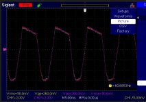
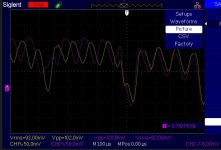
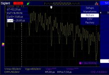
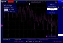
Hi peufeu, thanks for all the tips. I took some readings tonight and I did not blow up the amp or my oscope, but thanks for the warning, (I have made that mistake before poking around a guitar amp with 2 probes. I am attaching some pics. The first is what I get when both amp inputs are shorted and probes are on + speaker terminal of each amp, (probe grounds attached to safety/earth ground.) Pic. 2 is a composite of the two waveforms at the resolution of switching, I believe just under 200kHz. I notice that they start to align after a couple cycles. Pic 3 and 4 show a close up of each waveform, with cursors measuring 10 cycles. According to my math ch.1 is switching at 191.6kHz and ch.2 at 192.7. The delta is 1.2kHz which is about double what I am hearing at the speakers, but may confirm your hypothesis. I hope to get to the other tests tomorrow.
Hi peufeu, thanks for all the tips. I took some readings tonight and I did not blow up the amp or my oscope, but thanks for the warning, (I have made that mistake before poking around a guitar amp with 2 probes. I am attaching some pics. The first is what I get when both amp inputs are shorted and probes are on + speaker terminal of each amp, (probe grounds attached to safety/earth ground.) Pic. 2 is a composite of the two waveforms at the resolution of switching, I believe just under 200kHz. I notice that they start to align after a couple cycles. Pic 3 and 4 show a close up of each waveform, with cursors measuring 10 cycles. According to my math ch.1 is switching at 191.6kHz and ch.2 at 192.7. The delta is 1.2kHz which is about double what I am hearing at the speakers, but may confirm your hypothesis. I hope to get to the other tests tomorrow.
Attachments
Now attention is off the PS and on the shared input signal ground I thought I would connect a simple RadioShack ground loop isolator. Problem ostensibly solved. No audible noise at speakers with 2 class D amps and stereo input from iPod. I have yet to try this with a source whose ground is also connected to earth ground, as will be the case in final implementation. Combining the collective contributions of all posters, it seems most likely that the differences in switching frequency is inducing currents that make their way through the signal ground. I know, this was stated at the start and throughout.
Unless there are other suggestions for how to address this problem, it seems a simple audio transformer in series with input is the answer. Has anyone had good experience with this?
Thanks again for all the contributions.
Unless there are other suggestions for how to address this problem, it seems a simple audio transformer in series with input is the answer. Has anyone had good experience with this?
Thanks again for all the contributions.
Last edited:
Yeah that's what I thought. Each amp draws switching current from its supplies. With symmetric supplies it would be somewhat less of a problem, but with only one positive supply, these currents go through the shared ground and make a mess. It's not possible to run this kind of amps without a balanced input. I wonder why they sell them with an unbalanced input.RadioShack ground loop isolator. Problem ostensibly solved. No audible noise at speakers with 2 class D amps and stereo input from iPod.
And so their stereo and 3-way models use the same switching timer for all output stages? Well, this has been an interesting but ultimately disappointing experiment. I am not sure what kind of fidelity I will lose using input xos/ground isolation. Thanks for the help.
If the layout is good, it's possible to make a single supply, single board multichannel amp with all the single ended inputs standing on the same ground plane, on the same side of the pcb, at the same potential. All the high power stuff goes on the other side of the PCB, so the currents don't circulate in the ground plane near the IO connectors, which means all their grounds are at the same potential, which solves the problem... somewhat. That's a big reason why most class D amps have a balanced input.
But it's not possible to do it with multiple boards because then you have wires with high current flowing in them, and each board has its own "ground" potential which is different from the others, and each board has a single ended connector sitting on it connected to its "ground"...
Class AB stereo amps usually have positive and negative supplies. If they are made with one board per channel, the current in ground wires between these boards is simply the output current, it is not distorted. This mitigates the problem, so it is possible to make dual supply amps with one board per channel. But not single supply...