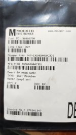
I changed the power supply MOSFETs to IXYS IXTH34N65X2 N-Channel X2 MOSFETS - 650V, 34A, as the Vishay IRFP27N60K are End of Life: Scheduled for obsolescence and will be discontinued by the manufacturer. The IXYS part exceeds the Vishay part in both voltage (600v) and current (34A) and is comparable on many other specifications. So far, so good. It has fired up ok - the test lamp dipped to a reasonable level, however, still quite a high pull.
I also replaced all of the IRFP240 / 9240, with all new, with similar gate thresholds per side (3.18V / 3.36 respectively). I noticed that the originals were matched, in the region of 3.42V for all devices. The power amp blocks seem to be getting very warm - I imagine this is to do with both sides running, and bias current being excessive. There is an adjuster, which I imagine adjusts the cross-over point, and therefore bias - I will attempt an adjust on this tomorrow.
Thank you all, especially Steve Smith
A snubber (or two) is probably a good idea. However, all of the power supply failures I have repaired have been caused by something else failing first. Usually a pair of output transistors, or in one case, the +/-80v supply rectifiers.
All of the Little Mark II amps I have repaired had higher specification IRFP27N60 transistors in the PSU rather than IRFP460 which I have only found in a lower power model (can't remember the model name).
Steve.
I've got the bias set to around 25mA per device - starts at 30mA ish then compensates down to around 22.5-25mA (like I said the up to down aren't really matched). Temperature rise isn't massive now, think I'm going to jack into the return with a signal & find the cross-over point at cold, then warm.
So you know - turning the multi-turn clockwise reduces bias, ant- increases bias, so if it's too warm, give it a few turns forward to start with, but you really do need to do this by signal generator and oscilloscope to get the most power out, with minimum x-over distortion. I might set it so that you still get a little distortion at cold - the blocks are warming up nicely - up to about 37 degrees C.
I worked out the new bias voltage by measuring the gate threshold of the old working devices that came out with a Peak DCA55, and then the new ones that were going in. outgoing were 3.42V up and down, incoming were 3.18 and 3.36, which is a difference of 0.28V. I wired up test leads to the 1 gates let the amp settle - the block was getting hotter, so I stopped it when it felt warm to the touch, then reduced the voltage by
I've had this on a fan-cooled 400W load for a good while - the fan has gone up and down with the block temperature well enough, though I can't help but think using a fan per block might be a better idea - the air cannot circulate around this enclosure well. There's definitely space for the fans - I imagine they were designed in, then pinched out by the money people.
I spoke to an engineer in company who would have been able service these (a suitably vague description), and apparently they'd heard that bias spec was around 30mA per device, which sounds bonkers, but is around where the bias would have been set from the calculations above . I now have it set to 1.5mV / 4.5mA on positive / up, 2.0mV / 6mA on the negative / down. The overall difference between gates is 6.12V. I've tried it at near quiescence, and full belt limiter levelled, as low a note as I can hear, +1 decade, + 2 decade, all fine , no x-over distortion. I would have gone lower, but 25% difference (now it's cool it's more like 20%) in bias is kind of where I'm happy.
They're now cooling down to tepid, which is much nicer starting point. I know no-one in their right mind would run the amp at 40-55Hz or so constantly.
I can't see the point of fitting fuses without fitting fans, and there just isn't the money in the job - probably a lot cheaper to just replace the switched mode transistors if they pop again. The idea or re-routing the opto supply so that I can fit fuses also doesn't appeal. I think the best thing is to keep the bias lower, and at least give a bit more headroom for the blocks to cool down into, and also a bit more headroom on the output, which was a bit poor.
Anyway, I'm going to tidy up my test leads, but leave them on, just in case.
From my experience.
The IR2153 is a bad i.c.
The biggest problem is the absence of an integrated soft start circuit.
Because of this you need a mosfet or IGBT with huge pulsed collector current.Icpulse
I have big troubles 😭 repairing a smps that always start normally with a series protection lamp but failed again and again when no protection lamp in series with the main.
The solution?
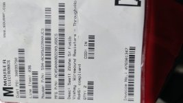
I used two non flammable fixed resistors in series instead of n.t.c (it is a relay that short this as soon as a voltage is present in the secondary)and two huge very expensive IGBT.
The IR2153 is a bad i.c.
The biggest problem is the absence of an integrated soft start circuit.
Because of this you need a mosfet or IGBT with huge pulsed collector current.Icpulse
I have big troubles 😭 repairing a smps that always start normally with a series protection lamp but failed again and again when no protection lamp in series with the main.
The solution?
I used two non flammable fixed resistors in series instead of n.t.c (it is a relay that short this as soon as a voltage is present in the secondary)and two huge very expensive IGBT.
Attachments
Last edited: