Re: Re: current limiter and others
Only one problem with that. There too slow, you'll blow the supply before the thing even knows what to do.
That would work in a supply that can take short term abuse with no problems, but smps don't like abuse, hence why they usualy have several protection systems.
MatthewS said:
A simple panel mount circuit breaker? drill a hole and attach two wires. It's a great 'afterthought' type of solution.
- Matt
Only one problem with that. There too slow, you'll blow the supply before the thing even knows what to do.
That would work in a supply that can take short term abuse with no problems, but smps don't like abuse, hence why they usualy have several protection systems.
Hi
Any update?
I got problem now, I rewinded trafo, make supply to work all the time, but now my startup circuit doesnt start to oscilate, so TL doesn't get power and nothing starts
left at the bottom, probably is something like that...what can I do?
Any update?
I got problem now, I rewinded trafo, make supply to work all the time, but now my startup circuit doesnt start to oscilate, so TL doesn't get power and nothing starts
left at the bottom, probably is something like that...what can I do?
Reliable self-oscillating startup requires some particular circuit conditions. Could you post the exact schematic and component values that are not working?
Note that the schematic that you have posted relies in a separate standby flyback supply for startup rater than self oscillation of the main supply.
Note that the schematic that you have posted relies in a separate standby flyback supply for startup rater than self oscillation of the main supply.
Hi Luka
Yes , I build the current sensor and another things. I think it's a "update"...
About your ATX schematics, sorry, but I don't like PC power supplies because the transformerless starter, in all my projects I built with a small transformer (150mA) to run the PWM CI and buffers with grounds together or not.
Thank you.
I started loving self oscillating startup the day that I finally understood in detail how it worked 😉 Then I was able to get it to work in a repeatable way. It's great as long as very low duty cycles are not required during normal operation (like during a short circuit with continuous current limiting).
Hi
I was really trying to avoid drawing schematic, this board are so small, every pin has multiple connections to others all over the place...but if nothing else could be done...
Funny thing is that if worked, until the one time after I have checked secondary with scope. Also dead time...it is a bit large, and I don't really know how to change it in TL. But startup is first to be fixed...ooo jea no apparent blown or black components. All I hear now is some low freq like pulsating freq. comming from somewhere in primary side

Little tweaking of my ATX PSU
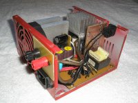
I read with interest this thread. I am not at all an expert in this field, but occasionally does hobby projects. Things started when I bought 2 battery chargers through ebay each with 15A rating. They both were running extremely hot even on no load and one of them just blew up. So I decided to modify an ATX power supply unit and make a PSU of myown . I got one with 400W rating with 17 amp for 12V rail. I had to fiddle with it for several hours and I did:
1. Disabled the powergood module- It was controlling the swithing MOSFET thru an optocoupler, which I connected direct to 5v supply thru a resistor and making it switched on permanently.
2. Identified the feedback circuit which was based on AZ431. It had feedback from both 5v and 12v rails. Disconnected from 5v and rearranged the resistor network to get feedback only from 12v rail and to get output voltage of 13.7
The output voltage was remarkably constant with less than 20mv variation over wide output currents.
I think it is based on a flyback topology with single swithing MOSFET (correct if I am wrong) and seems to be capable of 300 - 400W power. I even tested the 12v with over 35A for 2 sconds without issues. The problems I face are
1. I can't get all of the power it can deliver because the 12V winding of the transformer may be of thinner wire and may get overheated with >17A; the shottkey rectifier diodes are 20A which gets hot even at 10-15A.
2. There is no simple means of current limiting. I saw a simple circuit of putting 0.1E resistors and transistor. But it is difficult to incorporate 3 or 4 big 10W resistors in an ATX cabinet.. Is there any simple external current limiting circuit using transistor or mosfet without actually connecting to the smps feedback control, but acting as a series variable resistor if currentflow exceeds the limit.
Any comments or suggestions welcome
thanks
Siby
Hi
I don't think you can go without full current going through let say transistor, which would with resistor limit output current to set one, but!!!: Transistor would dissapate heat as would resistors. This is with no influence to FB, then you can use circ above and one more, current sensing by trafo...maybe some other way to, but can't think of any now
I don't think you can go without full current going through let say transistor, which would with resistor limit output current to set one, but!!!: Transistor would dissapate heat as would resistors. This is with no influence to FB, then you can use circ above and one more, current sensing by trafo...maybe some other way to, but can't think of any now
They are usually forward converters, flyback is very problematic at high output currents and powers. If there is an inductor for the main outputs it is a forward converter.
It is probably a current mode supply. You could increase the source resistor for the primary side mosfet to get a lower current limiting point. You lose a small amount of loop gain but it shouldn't really be a problem. I don't know if it will run like that though or shut down when it hits the current limit point. It should be easy to test. Doubling the resistance halves the current limit point.
"1. I can't get all of the power it can deliver because the 12V winding of the transformer may be of thinner wire and may get overheated with >17A; the shottkey rectifier diodes are 20A which gets hot even at 10-15A."
Pushing it a little bit over the rated value shouldn't be a problem for the transformer, especially if the +5 and +12 windings are stacked. (they usually are!) How hot does the rectifier get? It might be possible to steal a higher rated diode from another output as long as its voltage rating is high enough for the 12V. Sometimes the power supplies use pretty strange non-obvious diode connections though. The 5V diode might be used in some way by the 12V output for example.
Thanks for your prompt replies.
There is a 40A diode for the 5V rail, which is rated 40V. Could I use this for the 12V rail? I was not not sure if the inverse voltage on the diode on the 12V winding could be more than 40V. The existing diode of 20A is rated 100V.
I was thinking on the same line. The reason why I didn't want to control the SMPS feedback for current limiting is because I am not an expert to do this. My idea was, passing the whole 12V output through a transistor set up outside the ATX PSU on a heat sink which normally is configured to be conducting with negligible voltage drop across and little heat dissipation. But the base bias is controlled by a simple circuit which actually monitors the currentflow by some mechanism (which I can't figure out how) and restrict the main transistor bias once the current flow exceeds the limit. So the transistor acts as variable resistor and will dissipate heat only when the current is excessive unlike a pure resistor. The other advantage that once I make this circuit, I can use it with any PSU irrespective of the voltage to limit the current, which adds a lot of flexibility. I shall try to post my idea as a diagram in a later postLUKA:I don't think you can go without full current going through let say transistor, which would with resistor limit output current to set one,
Yes, after a bit of 'research' I think mine is a forward converter (how ignorant I am!).megajocke: They are usually forward converters
I assume, you mean the resistor which is in series with the mosfet (about 5ohm I think). I am not very confident to alter the MOSFET circuitry, but certanly will test.You could increase the source resistor for the primary side mosfet
The diode is on a heatsink and gets so hot that I can't touch it (may be 80 - 90 degrees). It is rated upto 125 degrees.It might be possible to steal a higher rated diode
There is a 40A diode for the 5V rail, which is rated 40V. Could I use this for the 12V rail? I was not not sure if the inverse voltage on the diode on the 12V winding could be more than 40V. The existing diode of 20A is rated 100V.
Current limiter
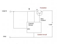
I am attaching a diagram to show my idea of external current limiter circuit. But I don't know how to make the control circuit. The resistor R can be of the order on 0.01 ohm (can even be a loop of wire as a resistor) so that even at 20A the voltage drop is only 0.2V and heat of 4W. that voltage drop is sensed by the control unit which then restricts the transistor bias and choke the input current. I want to know if it is practical or just a blunder.
I am attaching a diagram to show my idea of external current limiter circuit. But I don't know how to make the control circuit. The resistor R can be of the order on 0.01 ohm (can even be a loop of wire as a resistor) so that even at 20A the voltage drop is only 0.2V and heat of 4W. that voltage drop is sensed by the control unit which then restricts the transistor bias and choke the input current. I want to know if it is practical or just a blunder.
Attachments
Hi
No no not like that, it would be much easyer to make interface with FB then this... I was thinking of...same thansistor as you do have, resistor goes from C now to E. then you use PNP resistor that goes with....ah just see the pic, pic is good for 100 words 😀
BTW what you were thinking, that is so called high side driveing, you would have...it is more difficult
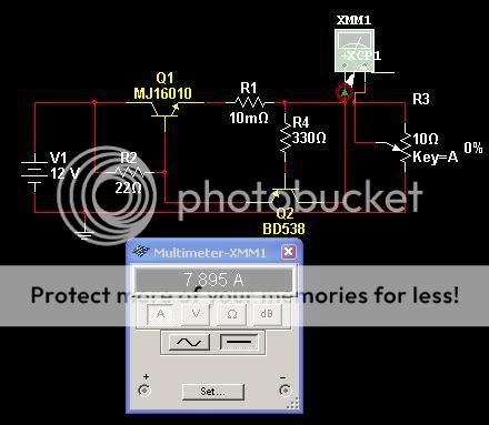
"I assume, you mean the resistor which is in series with the mosfet (about 5ohm I think). I am not very confident to alter the MOSFET circuitry, but certanly will test. "
That doesn't sound right. Are you sure you are looking at the resistor from source to primary side negative bus voltage? It will be less than 1 ohm. (remember Gold multiplier band = x0.1, Silver = x0.01)
"The diode is on a heatsink and gets so hot that I can't touch it (may be 80 - 90 degrees). It is rated upto 125 degrees.
There is a 40A diode for the 5V rail, which is rated 40V. Could I use this for the 12V rail? I was not not sure if the inverse voltage on the diode on the 12V winding could be more than 40V. The existing diode of 20A is rated 100V."
You can probably not do that then, if you want to uprate it you will probably need a 100V diode, the margin might be needed.
FYI, I find stuff too hot to touch already at 60 deg C. You might not expect that but above 40 deg C the sensation of heat goes up fast. 40 = warm, 50 deg is hot, 60 is really, really hot and 70 deg is won't-touch-that-again-hot if I remember correctly 😀
Thanks again for your prompt replies luka and megajocke.
I think my assumption of temperature was not that perfect and I now think the diode temp. may be 60 - 65 degrees 😀
I think incorporating suggestions from both of you should result in a pretty robust PSU
Siby.🙂
Yes, something of this kind was exactly what was in my mind, really this is much more simple. I assume the circuit is pretty reliable.ah just see the pic, pic is good for 100 words
You are right again, the resistor seems to be 0.18 ohmAre you sure you are looking at the resistor from source to primary side negative bus voltage
I think my assumption of temperature was not that perfect and I now think the diode temp. may be 60 - 65 degrees 😀
I think incorporating suggestions from both of you should result in a pretty robust PSU
Siby.🙂
- Status
- Not open for further replies.
- Home
- General Interest
- Car Audio
- Smps Car Battery Charger