Hi !
i have an audio interface here that has a noise issue.
And actually a guy with the same unit, after measuring this noise, has pulled out the smps from the case and the noise has gone away.
The ripple from the smps instead is nicely low and absolutely acceptable.
Therefore it seems clear that the noise originates from an imperfect shielding of the smps.
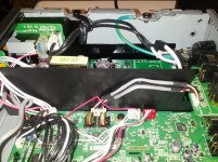
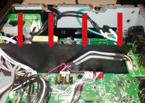
I am attaching picture of the smps.
I wonder if there is a way to spot the part who is generating this issue and add some shielding to tame this noise.
Another solution would be to extract the smps but that complicates the unit.
Moreover i see a multiwire connector going to the pcb with circuits.
So replacing this smps with a linear (may 1st idea) without having the schema could be difficult.
Advice are very welcome and appreciated.
Thanks a lot indeed.
Regards, gino
i have an audio interface here that has a noise issue.
And actually a guy with the same unit, after measuring this noise, has pulled out the smps from the case and the noise has gone away.
The ripple from the smps instead is nicely low and absolutely acceptable.
Therefore it seems clear that the noise originates from an imperfect shielding of the smps.
I am attaching picture of the smps.
I wonder if there is a way to spot the part who is generating this issue and add some shielding to tame this noise.
Another solution would be to extract the smps but that complicates the unit.
Moreover i see a multiwire connector going to the pcb with circuits.
So replacing this smps with a linear (may 1st idea) without having the schema could be difficult.
Advice are very welcome and appreciated.
Thanks a lot indeed.
Regards, gino
Attachments
Last edited:
If you contact TEAC and this is an issue, they will advise accordingly.
Hi ! thanks for the reply.
Someone else has already contacted Teac and they say that this is a marginal issue not impacting the functioning of the unit.
And actually the unit works. Not very classy answer by the way.
Maybe because this is a cheap unit and cannot be perfect.
It would create problem to more expensive ones.
Poor people must suffer ... 😉
However the interesting part is that if there were a dc socket on the unit a decent external smps could have solved elegantly the issue.
I am re-evalueting the classic wall adapters a lot.
The guy tried a 12VDC smps from Seasonic with very good results in terms of residual ripple.
A 20-25 USD piece and a dc socket would have solved the issue completely.
And the unit could have been much smaller too (who design these units ?).
Then one would be free to use the power supply of choice.
I would do the mod myself but without schematic of the power supply the risk is huge.
I do not want to fry the unit.
I love external power supplies immensely.
And in general power supplies are the component that fascinates me more. More than anything else.
Kind regards, gino
Last edited:
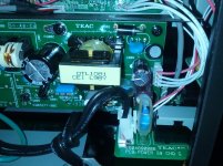
are you sure your smps gives you only 12 DC ?
it looks like multiple voltage output , a DC and a symmetrical +/- .
what TEAC device is that ?
.
it looks like multiple voltage output , a DC and a symmetrical +/- .
what TEAC device is that ?
.
are you sure your smps gives you only 12 DC ?
it looks like multiple voltage output , a DC and a symmetrical +/-
Hi ! no i am not sure.
I am a little scared about pull it out and measure. I understand there is high VAC involved.
The guy said 11.2 VDC and some of the connectors are linked together.
So i guess a single V out power supply can be used because it is what he did.
I will try to extract the animal ...
I would really like the dc socket option on the back.
Or another option could be going with AC to the unit and place a regulation stage inside. Nice and clean. With the polluting mains transformer out of the case. What puzzles me is they do almost everything very well and then skip on the last details that would make the product almost perfect. For nothing more.
what TEAC device is that ?
Product: UH-7000 | TASCAM
Regards, gino
Last edited:
It seems to be a simple fly-back SMPS. They are simple, and easy to controll, but generates very high level of capacitive disturbance. There is a common mode choke to attenuate this, but not surprisingly its not enough. Since moving away the psu helps, the conductive coupling is managed well, but very probably stray capacitance injects noise to everywhere. You can shield transformer and primary sides witcher, but special care is needed to preserve isolation strength, especially since the shielding must be connected to output GND. Maybe through a Y capacitor.
I would not be surprised to find a +48V rail on these as well as whatever the notional rails are (+,-15V to 18 or so), or maybe a logic supply if the phantom is generated on board.
I do not believe this to be a single +12V rail.
Regards, Dan.
I do not believe this to be a single +12V rail.
Regards, Dan.
It seems to be a simple fly-back SMPS.
Hi ! thanks a lot for the very helpful reply.
Before continuing there is an update. I checked the partition between the smps and the circuits board ... it is just a very thing sheet of plastic 😱
The other partitions i have seen they were all metallic.
I wonder what level of shielding a platic partition can provide, if any ...
I really would like to try something more effective.
They are simple, and easy to controll, but generates very high level of capacitive disturbance. There is a common mode choke to attenuate this, but not surprisingly its not enough.
Since moving away the psu helps, the conductive coupling is managed well, but very probably stray capacitance injects noise to everywhere. You can shield transformer and primary sides witcher, but special care is needed to preserve isolation strength, especially since the shielding must be connected to output GND. Maybe through a Y capacitor.
Thanks a lot again for the very kind advice.
I think i could do much more harm than good.
I see that other interfaces come with an external smps ... much more handy solution. In this way shielding is guaranteed.
I would like to extract the smps and put insted a linear regulation stage and using an external mains transformer.
Because from what i read this thing has a nice potential.
I hope some of the owners will pop up with a handy solution.
Strange that in Tascam has overlooked this issue. For them to solve it would have been trivial.
Thanks a lot again, gino
I would not be surprised to find a +48V rail on these as well as whatever the notional rails are (+,-15V to 18 or so), or maybe a logic supply if the phantom is generated on board.
I do not believe this to be a single +12V rail.
Regards, Dan.
Hi Dan ! thanks a lot for the kind and valuable advice.
I can find only TEAC E90327-00C written on it.
I wonder if a service manual with schematic is available from any vendor to see the actual voltages generated.
As i said this interface as a high potential for good sound.
A low noise linear supply with the transformer kept external, would eliminate any issue of intereference.
The space available can accomodate easily a good quality regulation stage.
The circuit board is very well designed, someone says.
Next time i will buy one with external ac adapter for sure.
I like to play with power supplies a lot. It is the only way i can do. 😱
Thanks a lot again, gino 😀
Last edited:
Have you tried just measuring the rails, there are only 4 wires, so probably three rails (I would guess +-15 or so, and a low current +48 for the phantom supply) ?
Secondly, what measurements have you made to establish that the switcher is the problem, and that the problem is radiated emissions, IME the issue is at least as often conducted in the MHz region.
Contrary to popular belief it is entirely possible to design a mic preamp with a switcher for a supply and have the switcher be completely blameless, not that it is a given but it can be done.
Regards, Dan.
Have you tried just measuring the rails, there are only 4 wires, so probably three rails (I would guess +-15 or so, and a low current +48 for the phantom supply) ? Secondly, what measurements have you made to establish that the switcher is the problem, and that the problem is radiated emissions, IME the issue is at least as often conducted in the MHz region.
Hi ! not yet.
Just to give the full information this is the test.
Tascam UH-7000 power supply noise
The guy has carried out a very basic but also extremely telling test.
He has recorded the silence of the unit. The silence must be silent by definition.
Then he has performed a very interesting FFT analysis ... here i am completely lost.
From test it is clear that the PS ripple is low but when placed in the chassis some noise pops up.
An external and well shielded adapter would have solved the issue completely.
Actually many other cheap interfaces are built with an external power supply and a dc socket on the unit.
Contrary to popular belief it is entirely possible to design a mic preamp with a switcher for a supply and have the switcher be completely blameless, not that it is a given but it can be done.
Regards, Dan
i think that the main goal has been to keep the unit compact and light.
Instead i like so much when a unit measures impeccably.
This unit from what i have gathered around has a huge potential for decent sound.
I am sure that a good linear power supply would give some benefit.
Sometimes the difference between good and excellent is in the details (that are not details).
Thanks again, gino
Last edited:
I am not at all sure I would call some hash at -150dBFs above the audio band a problem!
That said, if I wanted to make this go away, I would be starting with a high Mu ferrite sleeve on both the input and output cables from the power supply (Mostly because it is an easy a quick thing to try, and common mode noise is a thing in switchers), radiation @ 20Khz should not be a major thing in a low Z microphone circuit.
Speaking of low Z mic circuits, what did you have the inputs terminated into when making those measurements? Open circuit will tend to pick up far more random interference then a input loaded with 150 ohms or so from a mic will.
Regards, Dan.
I am not at all sure I would call some hash at -150dBFs above the audio band a problem!
Hi and thanks again for the helpful reply.
This was the reply from Tascam i understand. No impact on the actual performance.
If taking this hash out would be expensive i would accept it without problem.
That said, if I wanted to make this go away, I would be starting with a high Mu ferrite sleeve on both the input and output cables from the power supply (Mostly because it is an easy a quick thing to try, and common mode noise is a thing in switchers), radiation @ 20Khz should not be a major thing in a low Z microphone circuit
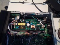
i would like to understand which parts in the smps could be generating this radiated noise. I mean, the test with the same exact ps extracted is perfectly clean. Perfect !
I see in the computers that the smps are enclosed in metallic cages.
I checked the partition separating ps and circuits ... it is just a sheet of very thin plastic !!!
i do not know if this is a special plastic but i guess its efficiency in stopping RFI/EMI should be near to zero 🙄
On ebay i have seen copper adhesive tapes for shielding , not plastic tapes. And some 3M high tech material that is very expensive.
So the idea would be to improve that partition working as a noise dam ...
Speaking of low Z mic circuits, what did you have the inputs terminated into when making those measurements ?
Open circuit will tend to pick up far more random interference then a input loaded with 150 ohms or so from a mic will.
Regards, Dan
i do not know. I just found the test on a unit that i also own.
But my guess is that all the graphs are obtained in the same exact testing conditions (i.e. open inputs and not terminated) to see the effects of using different external smps.
In one very positive case, the original smps was used but pulled out from the case. Noise disappeared completely !!!
So it must be a radiating noise picked up from some cables of parts on the circuit board.
If it were me i would go immediately for the Seasonic unit (no noise) and put a dc socket on the back of the unit.
Even without thinking just a second.
I would be so much happier than you do not believe. Notwithstanding what Tascam say.
Now i cannot live with that imperfection.
My main problem is that i have no clue about how to get those magnificient FFT curves ... i have asked but the answer was not enough.
The poster mentioned a sw ... Octave ... i have downloaded but i do not know how to use it at all.
I could check the impact of different mods quite immediately 🙁
Maybe i am sounding a little obsessed but this is by far the most interesting area for me at the moment.
I am evaluating different sound cards noise.
Thanks a lot again, gino
Attachments
Last edited:
I am not at all sure I would call some hash at -150dBFs above the audio band a problem! ... Regards, Dan.
Hi Dan ! just to say that the Y scale is wrong ... on another blog
Archimago's Musings: MEASUREMENTS: Tascam UH-7000 USB Interface (Part II: As an ADC)
i found this result ... still low but higher than previous one.
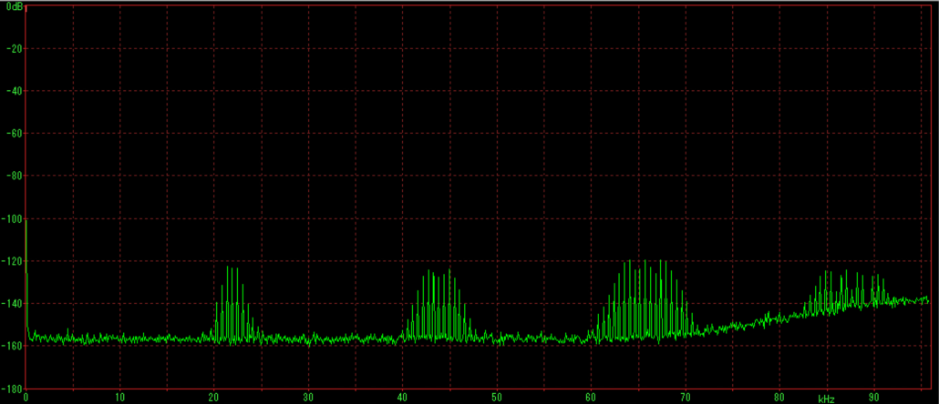
See that wonderful base line at -160 dB 😱
 😱
😱i dream one day to get there ... the perfect unit.
However similar overall conclusions.
Bad shielding of the smps is causing the noise.
This for me is completely crazy on a audio unit.
Just put a shielded smps inside ... what is the problem ??? i really do not understand.
In USA this amazing thing costs almost nothing.
In Europe quite a bit more.
Regards, gino
Last edited:
Bear in mind that the energy per FFT bin depends on the number of points in the FFT, I can get arbitrarily low per bin levels by using lots of bins.
The measure you want is not how far down the baseline is in some arbitary FFT, but where the baseline is expressed as noise in a specified bandwidth or noise power per Hz.
Seriously, try some clip on ferrite sleeves on the power supply cable bundle, also fitting a conductive bulkhead where that plastic divider is (bonded to the chassis on at least three sides) and with an insulating surface facing the power supply (No point in encouraging short circuits), copper foil stuck to the side of that plastic sheet facing the main board seems likely (With appropriate bonds to chassis).
Is this thing a class II device, I ask because that plastic divider is making me think it may be additional insulation for compliance.
As to why design like this, they had a performance spec and did what they needed to do to meet it, and actually all the power supply hash is up in the ultrasonic and is low level anyway, not the sort of thing I could get excited about.
For most of us, most of the time, meets spec and BOM cost is the objective, not is as good as we can possibly make it.
Regards, Dan.
Bear in mind that the energy per FFT bin depends on the number of points in the FFT, I can get arbitrarily low per bin levels by using lots of bins. The measure you want is not how far down the baseline is in some arbitary FFT, but where the baseline is expressed as noise in a specified bandwidth or noise power per Hz
Hi thanks a lot for the kind reply.
I tried to understand this FFT issue but failed. Too difficult.
I only see the three annoying bumps at 22kHz and multiples.
It would be nice to have a flat noise line without bumps. This was my dream.
I think that the real noise base line is at around -140 dB more or less.
The bumps are about 40dB. Big bumps indeed.
Seriously, try some clip on ferrite sleeves on the power supply cable bundle,
do you mean on the AC cables ? i do not think that DC cables need ferrite sleeves. I will do that for sure. I will buy some of them to try out.
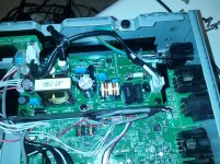
also fitting a conductive bulkhead where that plastic divider is (bonded to the chassis on at least three sides) and with an insulating surface facing the power supply (No point in encouraging short circuits), copper foil stuck to the side of that plastic sheet facing the main board seems likely (With appropriate bonds to chassis).
sorry what is a bulkhead ? i do not understand.
The problem with the plastic sheet is that is very thin and flexible. Not a good support for anything at the point that i was thinking to a new one maybe in aluminum ? just to serve as a more stable support for the copper foils (maybe one on each side of the sheet). The original is very flimsy.
Is this thing a class II device, I ask because that plastic divider is making me think it may be additional insulation for compliance.
As to why design like this, they had a performance spec and did what they needed to do to meet it, and actually all the power supply hash is up in the ultrasonic and is low level anyway, not the sort of thing I could get excited about.
I see. But my point is that i would expect that the emissions for a smps intended for an audio unit were very low. I mean some more shielding could have solve nicely the problem and the same exact smps can serve very different models. But i see your point.
For most of us, most of the time, meets spec and BOM cost is the objective, not is as good as we can possibly make it.
Regards, Dan
Thanks a lot again. I would do anyway the test with the am radio ... i am very curious to see if the buzz will change point the antenna in different points on the smps pcb ... very curious.
Another thing i have not checked is some cables that run close to the smps and end on the circuits pcb. They could act as antennas and discharge the noise in the circuits pcb. Again really strange routing. I do not understand.
I am more and more convinced about external power supplies ... keeping all the garbage out of the circuits box. Very sane decision.
Thanks a lot again, gino
Attachments

Possibly, but my bet would be that clamping a sleeve around that bundle of 4 DC cables will be the one that matters.do you mean on the AC cables ? i do not think that DC cables need ferrite sleeves. I will do that for sure. I will buy some of them to try out.
External power does not do well in the marketplace, and those combs are all ~100dB down and in the ultrasonic, why do you care about them?
A metal bulkhead between the supply and the main board might help, but if the device is class II you will want to ensure that the power supply still has appropriate secondary insulation.
I think you are looking at an FFT plot, not really understanding it and panicking about a non issue.
Regards, Dan.
Possibly, but my bet would be that clamping a sleeve around that bundle of 4 DC cables will be the one that matters.
Thanks again. However i am very decided in the weekend to extract the ps and at least make some photos. I am a little scared to power it but i will see. In particular if i have understood well the 4 DC cable has three wires carrying the same V+ (around 11.2 VDC) and one ground. I have to check.
If this is the case any single DC power supply could replace it.
Smps are usually more noisy than linear.
External power does not do well in the marketplace,
some interfaces have a dc in with external adapter.
After this experience i would not have the least doubt. External always.
and those combs are all ~100dB down and in the ultrasonic, why do you care about them?
A metal bulkhead between the supply and the main board might help, but if the device is class II you will want to ensure that the power supply still has appropriate secondary insulation.
I think you are looking at an FFT plot, not really understanding it and panicking about a non issue.
Regards, Dan
found another link to same issue ...
Amazon.com: G. M. Leong's review of TASCAM UH-7000 High Resolution USB Interfa...
The SMPS create high frequency floor noise which can be easily measured using software like ARTA
if only i knew how to measure 😱 ... interfaces are my only true interest, together with power supply noise of course 🙂
However even with a linear ps the transformer would stay absolutely out ... no EMI generator inside.
Complete quietness.
Thanks again, gino
Apart from the transients at the recovery of the rectifier diodes.... Also you power supply is no longer universal input.
Also, set up a microphone that has a response into the ultrasonic and look at the actual noise floor, that switcher will probably vanish into the mess up there.
If you start looking at the complete system, you will find that the things to worry about are probably not what you think.
Regards, Dan.
Also, set up a microphone that has a response into the ultrasonic and look at the actual noise floor, that switcher will probably vanish into the mess up there.
If you start looking at the complete system, you will find that the things to worry about are probably not what you think.
Regards, Dan.
Apart from the transients at the recovery of the rectifier diodes.... Also you power supply is no longer universal input.
Also, set up a microphone that has a response into the ultrasonic and look at the actual noise floor, that switcher will probably vanish into the mess up there.
If you start looking at the complete system, you will find that the things to worry about are probably not what you think.
Regards, Dan
Hi! i will follow your advice and do not change anything.
But i was also thinking to those wires all over the place.
Assuming that:
1) the Vout of the smps is quite clean because i have seen tests showing this
2) the plastic sheet works ok in stopping smps radiated noise from reaching the pcb with circuits
the only way the noise radiated from the smps can reach the pcb is through wires that run close to the smps and end at the pcb (i.e. acting like antenna)
Could it be that re-routing these loose wires and maybe wrapping them in some kind of shield can work ?
Another issue. The guy who has replaced it with a linear has carried-out some measurements of the noise using the Arta software.
Is using this SW difficult ? Do you know it ?
This would be interesting in general for me because i am selecting some interfaces and noise measurement could be an interesting method of comparison.
Thanks again, gino
- Status
- Not open for further replies.
- Home
- Amplifiers
- Power Supplies
- SMPS _ shielding options.