still4given said:I have a few pics of my case.
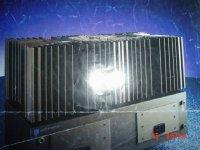
Great looking chassis, Terry.
What is the weight of the transformer ?
The Drooler
still4given said:
I can easily reduce the length of the caps but are you telling me that the ones I used are no good for this application? I don't recall ceramics being called out in the BOM. Things like this should be said before us folks go out and buy and install parts IMHO.
One thing I have found is that the through plated holes, while very nice, are a pain in the rear end when it comes to replacing parts. It is very difficult to remove all of the solder from them.
Terry,
Your caps are fine, I was just refering to the safety of you placement - I use MMK (film) caps on the rails.
You should get yourself a good old solder remover with pump action. This helps a lot when working with plated holes.
The right tool(s) for the job is a must!
\Jens
JensRasmussen said:
I only use ceramic caps at work. They are excelent because they have very low ESR and ESL. They are however very nonlinear as their value changes a lot depending on what voltage is applied to them.
Don't be tempted to use ceramics for the Cdom in the VAS!
\Jens
Agree. Don't use typical disc ceramics at all, especially in the VAS. They are very non-linear and microphonic. Micas are probably best for VAS, especially for such small values. NPO ceramics, on the other hand, are very linear, temperature-, frequency- and voltage-wise. They are nothing like their disk cousins. Still not sure about their microphonic issue, but they are better than the disk type, which I why I wouldn't risk them in the VAS stage. As RF bypasses, microphonics, if any, may not be that important. The low ESR and ESL of NPO ceramics would be beneficial in bypasses.
still4given said:
Hi pooge,
I can easily reduce the length of the caps but are you telling me that the ones I used are no good for this application? I don't recall ceramics being called out in the BOM. Things like this should be said before us folks go out and buy and install parts IMHO.
One thing I have found is that the through plated holes, while very nice, are a pain in the rear end when it comes to replacing parts. It is very difficult to remove all of the solder from them.
I am not sure, but I think I read that an E-core transformer need to be turned in a certain direction due to it's magnetic field. If someone knows please instruct me before I bolt this one in.
Thanks
I don't know what caps you used, so I'm not saying they are wrong. If they are the correct value, they will work. I'm just saying that as bypass caps, low inductance is warrented for working the best. If they are stacked film types, that's what you want in a film cap, because the plates are stacked into a low inductance arrangement compared to a wound capacitor.
As Jens stated, you need a solder "sucker" /desoldering tool to clean the solder out when making repairs. They used to be available at Radio Shack. Probably still are. Practice with it on a throwaway board first. The key to using them is let it get fully hot first. Squeeze the bulb before placing it against the hole, then release the bulb quickly after the solder melts to suck out the solder. Clean it before each use by sharply squeezing the bulb to blow out the solder from the tip.
Regarding your E-core, they do emit more in certain directions than others. Also, certain direction of the plug will capacitively couple more noise to the chassis than the other direction. Test this first, before finalizing the hot and neutral wires on the plug. This can be done with any transformer. Wire the plug normally, with the proper hot, neutral and ground colored wires connected to the proper hot, cold and ground prongs on the plug, if they are not prewired. Connect the hot and neutral wires to the tranformer primaries with the transformer mounted in its final resting place. Do not connect the ground to the case yet. Plug in the transformer to power it, and measure the AC voltage between the case and ground wire. Reverse the wires to the transformer primary and measure the voltage again. Pick the orientation of the hot and neutral wires that gives the lowest case to ground voltage. This will lessen the ground current noise in your amplifier.
pooge said:
Agree. Don't use typical disc ceramics at all, especially in the VAS. They are very non-linear and microphonic. Micas are probably best for VAS, especially for such small values. NPO ceramics, on the other hand, are very linear, temperature-, frequency- and voltage-wise. They are nothing like their disk cousins. Still not sure about their microphonic issue, but they are better than the disk type, which I why I wouldn't risk them in the VAS stage. As RF bypasses, microphonics, if any, may not be that important. The low ESR and ESL of NPO ceramics would be beneficial in bypasses.
NP0, X5R, X7R, C0G and so on are the temperature coefficients of the device material....it says nothing about how linear it is vs. applied voltage or freq!!!!!. There are differences when looking at different packages like 0603 0805 1206 and so on, but generally they all have terrible DC bias characteristics that make them unfit for use in the signal chain of any audio equipment with big voltage svings! Micas, styroflex and other highly stable materials are far better for this and IMHO ceramics are best for decoupling.
Try and download this excelent program from murata it tells the story about the different types of ceramics.
http://www.murata.com/designlib/mccdl_e.html
\Jens
jacco vermeulen said:
Great looking chassis, Terry.
What is the weight of the transformer ?
The Drooler
The transformer weighs 14lbs. I'm not sure what the vA rating is. In the Hafler XL-280 that it is designed for it puts out 140WPC. Hard to imagine it won't tun this amp. I'm not going monoblock. What you see is what I plan on except I am going to try and build a regulator for the front end. The filters on the boards are 80v 15000uf each and the larger screw terminal caps are 80V 27000uf each. I have two more of the 27K caps if I need them but hope these two will suffice.
Hi Terry,
use the extra 27mF caps.
Use two sets of rectifiers and then +-27mF after each rectifier.
This way you have monoblock from rectifier all the way to output. Just the transformer primary and secondary are shared. Not as good as monoblock in a single chassis but approaching it.
Single chassis saves on transformer and chassis and soft start and front end regulator PSU and rf rejection. A significant cost saving for only a small loss.
re your transformer, if it could do 140w+140w in a Hafler then it won't manage 200w+200w in this Leach. This indicates that your PSU voltage will collapse when you load both channels. However you intend using this for domestic music and in this duty the voltage on the rails will hardly waver and with two rectifiers the loaded channel cannot drag down the unloaded channel. Use it as is and see what performance you get out of it.
I just weighed the chassis and it weighs 14lbs without the transformer so this thing is going to weigh almost 30lbs. Kind of heavy for such a small watage amp.
Andrew,
As to removable panels, all of the panels mount to the heatsinks so each panel can be removed seperately without removing the others except for the heatsinks themselves.
I have two deloldering tools. One has a plunger and a spring release and the other is the bulb type. I still stand by my earlier statement that thru plated holes are more difficult to desolder. Teaches you to use the right part first time. 😀
Blessings, Terry
JensRasmussen said:
NP0, X5R, X7R, C0G and so on are the temperature coefficients of the device material....it says nothing about how linear it is vs. applied voltage or freq!!!!!. There are differences when looking at different packages like 0603 0805 1206 and so on, but generally they all have terrible DC bias characteristics that make them unfit for use in the signal chain of any audio equipment with big voltage svings! Micas, styroflex and other highly stable materials are far better for this and IMHO ceramics are best for decoupling.
\Jens
COG(NPO) are Class 1 ceramics and are stable with voltage. They are one of the most stable capacitors. Also, their DA is similar to mica and films. The ceramic is not based on barium titanate, so they are not as piezoelectric as normal ceramics. However, despite searching for info on this, I have not been able to find out their degree of microphonics or piezoelectric effect.
(X7R, Z5U and Y5V) are Class 2 ceramics, and based on barium titanate. They are not it the same league as Class 1. I wouldn't even consider these. The heat of soldering can change their characteristics.
See:
Ceramic caps
I don't want to sound like I'm am pushing these. I merely suggested them as a possibility. But I would only consider Class 1 types.
still4given said:I have two deloldering tools. One has a plunger and a spring release and the other is the bulb type. I still stand by my earlier statement that thru plated holes are more difficult to desolder. Teaches you to use the right part first time. 😀
AMEN! Haste makes waste, and high shipping costs!
still4given said:The transformer weighs 14lbs.
A 500VA EI-core weighs about 18 lbs, your transformer will likely be 400VA or less.
In those days it was common practice to employ transformers with a rating equal to the 4 ohm continuous power rating.
(i used to calculate all kind of ratio's of commercial amplifiers; $MSRP/VA, lbs/Watt, VA/Watt, and plot these into charts, and that was before the arrival of Excel sheets, what a nut !)
For a 140W/8 Hafler a 200 Watt/ch transformer is what to expect, and Hafler's were economy designs.
A toroidal transformer can push out twice its nominal rating if necessary and is able to keep voltage up better than standard EI-cores.
There are plenty of designs that employ toroids with 1.5-1.6 times the continuous 8 ohm power rating, and perform well.
I can give you examples also of commercial products that were upgraded with larger toroids, that had improved performance.
Even if the Hafler transformer would be rated at 500VA you should expect performance of your Leach with the Hafler transformer to be less than what could be achieved with an equal size or larger toroid.
iiwy, i'd be on the lookout for a toroid candidate, all the work and cash you invested in the rest of the amplifier is well worth it.
pooge said:COG(NPO) are Class 1 ceramics and are stable with voltage. They are one of the most stable capacitors. Also, their DA is similar to mica and films. The ceramic is not based on barium titanate, so they are not as piezoelectric as normal ceramics. However, despite searching for info on this, I have not been able to find out their degree of microphonics or piezoelectric effect.
I stand corrected I just found some additional data regarding C0G/NP0 types...
look here: http://www.murata.com/articles/ta0381.pdf
\Jens
I have only seen these available in 5% tolerance packages - as opposed to the 1% tolerance packages offered by the silvered mica's. Will this have any relavent impact?
Otherwise these look like an excellent alternative - 1/10th the price of the micas in SA.
Otherwise these look like an excellent alternative - 1/10th the price of the micas in SA.
JensRasmussen said:
I stand corrected I just found some additional data regarding C0G/NP0 types...
look here: http://www.murata.com/articles/ta0381.pdf
\Jens
Thanks Jens. I've been looking for info like this. Although it is vague on what kind of film cap is tested, (probably polyester), it is heartening to see that the microphonics are low. I would have no problem in using these unless someone with experience using them relates some problems with them. As to Mica tolerances, they tend not to be 1% when getting down to super low values.
jacco vermeulen said:
A 500VA EI-core weighs about 18 lbs, your transformer will likely be 400VA or less.
In those days it was common practice to employ transformers with a rating equal to the 4 ohm continuous power rating.
(i used to calculate all kind of ratio's of commercial amplifiers; $MSRP/VA, lbs/Watt, VA/Watt, and plot these into charts, and that was before the arrival of Excel sheets, what a nut !)
For a 140W/8 Hafler a 200 Watt/ch transformer is what to expect, and Hafler's were economy designs.
A toroidal transformer can push out twice its nominal rating if necessary and is able to keep voltage up better than standard EI-cores.
There are plenty of designs that employ toroids with 1.5-1.6 times the continuous 8 ohm power rating, and perform well.
I can give you examples also of commercial products that were upgraded with larger toroids, that had improved performance.
Even if the Hafler transformer would be rated at 500VA you should expect performance of your Leach with the Hafler transformer to be less than what could be achieved with an equal size or larger toroid.
iiwy, i'd be on the lookout for a toroid candidate, all the work and cash you invested in the rest of the amplifier is well worth it.
Hi jacco,
This brings up a question in my mind. I have several power amps. Once in a while, while showing off one of them to a friend, I will crank up the volume a bit. My JBL's will really fill a room if you push them. Most of the time however, the amps run along at a fairly reasonable level. From what you and Andrew are saying, this Leach can put out more wattage than this Hafler transformer will be able to keep up with. My question is, is this going to be noticeable at reasonable levels or only when pushing it into say, a 4 ohm load? When the amp is not working hard, am I likely to notice a difference between 500vA and 400vA?
If the answer is yes, then I guess I'll look for a Torroid, but I would really like to use this transformer in something since I already own it. I also like the fact that it has a separate winding that is ideal for running a regulated front end.
You can see the specs for the amp here.
Blessings, Terry
The output level may not be significantly higher with a larger transformer but the sound quality will likely be superior. If you regulate the front end, other than the actual ultimate output level, the sound quality may not be significantly different with the larger transformer. If you're using JBLs in a domestic environment, I doubt that you'd be pushing the outer envelope of the ultimate power level. So good regulation may be all that is called for. It's a very subjective issue indeed.
Hi
Your transformer will be ok for your use , but you can increase the value of filter caps which can supply stored power when required , you will be feeding music and not sine wave .
Your transformer will be ok for your use , but you can increase the value of filter caps which can supply stored power when required , you will be feeding music and not sine wave .
Yep.
here is a picture of the French AudioAnalyse A90.
A 100 watt class A amplifier, burning more than 250 watts per channel.
On 330VA transformers, but it has 200.000 uF capacitors for each channel.
Bridged it does +400 in 8 ohms, +600 watts in 4 ohms.
Weighs nearly 100 lbs, on 16 Motorola TO3 cans it can do peak currents of 90 amps.
Attachments
Hi Terry,
for a domestic situation the small transformer will work OKish.
your amp running +-65Vrails deserves better. But remember what I said about 4 ohm loads at these voltages.
Two 400VA transformers would easily fit inside your case and you would then have full monoblock or alternatively a 800VA with four secondary windings at about 40Vac would give almost as good a result and drive any 4 ohm load into the bargain.
All is not lost though. You have a selection of good amps and I suspect some are better in some of the frequency range than others.
Try Bi-amping (not active) and select the amp that best suits the bass and another that best suits the treble and if you have a midrange then again the same applies.
The passive crossover will reduce the load on each amp and then they start to coast and the performance benefit in improved sound quality is worth the experimenting.
If you speakers do not have bi-amp terminals then get onto the speaker forum and start asking questions. That's that research I keep telling you about.
Mikett said:The output level may not be significantly higher with a larger transformer but the sound quality will likely be superior. If you regulate the front end, other than the actual ultimate output level, the sound quality may not be significantly different with the larger transformer. If you're using JBLs in a domestic environment, I doubt that you'd be pushing the outer envelope of the ultimate power level. So good regulation may be all that is called for. It's a very subjective issue indeed.
Hi Mikett,
When you say the sound quality will be superior, are you talking about all levels or mainly when being pushed. I have been opening up a lot of comercial amps lately to see what they are using for parts and it seems like they all use significantly smaller caps and transformers than everyone around here suggests. It seems like there is a "more is better" attiude around here. All of my Hafler and Soundcraftsmen amps use two filter caps. Guys around will stuff as many and as big as they can. Isn't there a limit to what can really be heard?
Are you guys building one of these? What size trans and filter system are you using?
What trans and caps are you guys spending your money on?
This trans is paid for. My four 27000uf caps are too. I need to use them somewhere. If not here, what amp design would this trans work good for?
Thanks, Terry
- Status
- Not open for further replies.
- Home
- Amplifiers
- Solid State
- Smaller Leach Amp V1