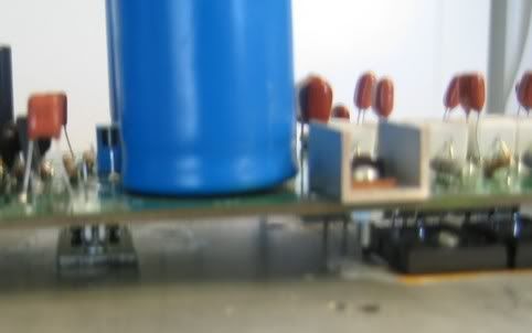
Here's the pic I promisied. As you can see they fit fairly easily. Whether or not to use them is you own decision.
Blessings, Terry
Blessings, Terry
still4given said:I do have a question though. Does the value of L1 matter all that much. Will an 8.2R resistor work there instead of a 10R? Isn't the resistor more just for a frame for the coil?
Thanks, Terry
The resistor should be ok as 8.2R... it is there to dampen any ringing in the inductor.
Nice looking boards btw. I hope to start soldering this weekend 🙂
\Jens
In the original Leach amp - C5 (Jens Board Numbering) was listed as being a 39pF Silvered Mica.
Can I ask if there a specific reason this has been changed to 47pF or is it simply that that was what was availalble?
Jens - just make sure to clean all that oxidation off of your soldering iron 😉.
I am still ages away from even having all of the components - but this time I am determined not to waste bucks - get the cheapest pricing! Except I already stuffed that up buy not ordering boards 😛
I also see the 390pF (Jens board numbering) cap has had it's type changed to Polyprop of Polyester as well as the value dropping to 330pF. Are there any comments on this?
Byrd said:In the original Leach amp - C5 (Jens Board Numbering) was listed as being a 39pF Silvered Mica.
Can I ask if there a specific reason this has been changed to 47pF or is it simply that that was what was availalble?
Byrd said:I also see the 390pF (Jens board numbering) cap has had it's type changed to Polyprop of Polyester as well as the value dropping to 330pF. Are there any comments on this?
I simulated the open loop freq response and found that this combination gives better phase margin than the original....
The Polyester cap is a lot cheaper than the mica (where I live)
\Jens
Thanks Jens - I knew there must be some reason.
I can tell you that those Mica's are VERY VERY expensive here as well. About $6 each. And when you are building so many channels it is a bank breaker.
I can tell you that those Mica's are VERY VERY expensive here as well. About $6 each. And when you are building so many channels it is a bank breaker.
Tony, if you have 200 Barbados Dale's, you've found a Carribean treasure. These resistors were highly praised by the writing people in those days.
thanks, actually i also have them labled MEXICO although longer by about 10mm....
Byrd said:I can tell you that those Mica's are VERY VERY expensive here as well. About $6 each.
I've been out of amplifier building for some 10 years,only been keeping track of Nelson Pass's doings, to discover the attention to silver-mica's on return.
Overhere use of silver-mica's died with the departure of tube equipment, in solid state fast precision caps used were polystyrene's.
The orange square Siemens B31531 styroflex i used then were about $5 for a 100pF cap.
about a month ago i bought a few hundred silver-mica's on Ebay, various size, for $0.20 the piece. It is tricky to find 1% or 2% accurate ones though, 5 % is easy.
imo, polyester/MKT capacitors should be avoided in the signal path, unless bypassed by MKP. Better is to use MKP only, turds like me bypass these with polystyrene's. Mr Grey Rollins posted he does the same, i consider him an authority with excellent ears.
Tony said:i also have them labelled MEXICO although longer by about 10mm
Would you like pictures of Mexico Dale's in vintage high end US amplifiers ?
They are the same type of resistors, i gathered.
At the time i was going over any article or brand folder with a magnifying glass for details, at first i thought Barbados was a brand.
It is safe to assume all of these greyish black Dale resistors are low inductance models.
And they are very rugged, they withstand a multitude of their power rating for several seconds.
still4given said:Well I've already soldered them in so I guess I'll hear it like this first. If I hear something bad I'll think about changing them.
I do have a question though. Does the value of L1 matter all that much. Will an 8.2R resistor work there instead of a 10R? Isn't the resistor more just for a frame for the coil?
Thanks, Terry
Terry, you may not hear anything bad with these resistors. I am just trying to build the best amp that I can, so I'm trying to get the best parts, not the cheapest, to match the quality of the boards. Along with the 1% tolerance and the non-inductance, the Mills have a TCR of 50ppm compared to the 300ppm that you are using. They have all welded construction for reliability and are non-magnetic. They are said to "sound" wonderful, but I have not directly compared them to others. Whether anyone wants to spend the extra money for them is up to them. The high-end police will not be knocking on your door if you don't.
The 8.2R resistor is fine. Leach actually raised this value from a lower value in previous versions of the amplifier. The lower value should work even better, according to Self, in its function as a damping resistor. Self showed that damping improved down to 1 ohm. Don't know why Leach raised it. Maybe it was because it is easier to obtain.
L1 value is also not critical. With the split feedback path in the Leach amp, L1 is not as important to prevent oscillation from capacitive loads as it would be if the feedback was not split. The value is around 1uH, which keeps output impedance down at higher frequencies compared to, say, typical 6 or 7uH values, which is about the limit for good extended frequency response, according to Self. Leach even said that L1 may not be needed with the split feedback. However, it is good to keep it there to prevent RF injection into the feedback path from the speaker cable antennas. Remember to use a non-magnetic resistor to wind L1 around, though, so it doesn't saturate. One trick I read is to wind L1 around a pencil, first, before sliding it on to the resistor. Makes it easier to wind.
Thanks guys,
I'll go ahead and use the 8.2R for L1. Leach shows R51 as 10R 2W. Is there a need for it to be 5W? I couldn't find any 5w at the store but I have 2W.
Thanks, Terry
I'll go ahead and use the 8.2R for L1. Leach shows R51 as 10R 2W. Is there a need for it to be 5W? I couldn't find any 5w at the store but I have 2W.
Thanks, Terry
pooge said:I'm trying to get the best parts, not the cheapest, to match the quality of the boards. Along with the 1% tolerance and the non-inductance, the Mills have a TCR of 50ppm compared to the 300ppm that you are using. They have all welded construction for reliability and are non-magnetic. They are said to "sound" wonderful, but I have not directly compared them to others
No objection here.
Using top quality resistors should mean less work for the feedback, less feedback adds less harmonics.
I've heard a design built with standard parts, and exactly the same design with every part matched and selected, big difference !
Hi guys,
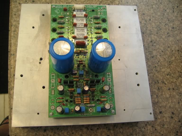
Well. as you can see from these pics, I am almost done with the boards. I would still like to try building a regulator for the front end if I can get a PCB together for it.
I may just install R1 & R23 so I can test to see if I've messed anything up.
I am still waiting for Jens to come up with a formula for getting the value of R68 & R69. That's all I'm missing on my boards. If someone can just give me the value for them I'd be fine with that. 😀 I should be running 65V rails.
Oh yeah, Does anyone know what was planned for F3 & F4?
One more question. If you install F1 & F2 and one of them blows and not the other, what happens to the DC offset? Would the speakers be in jepoardy?
Thanks, Terry
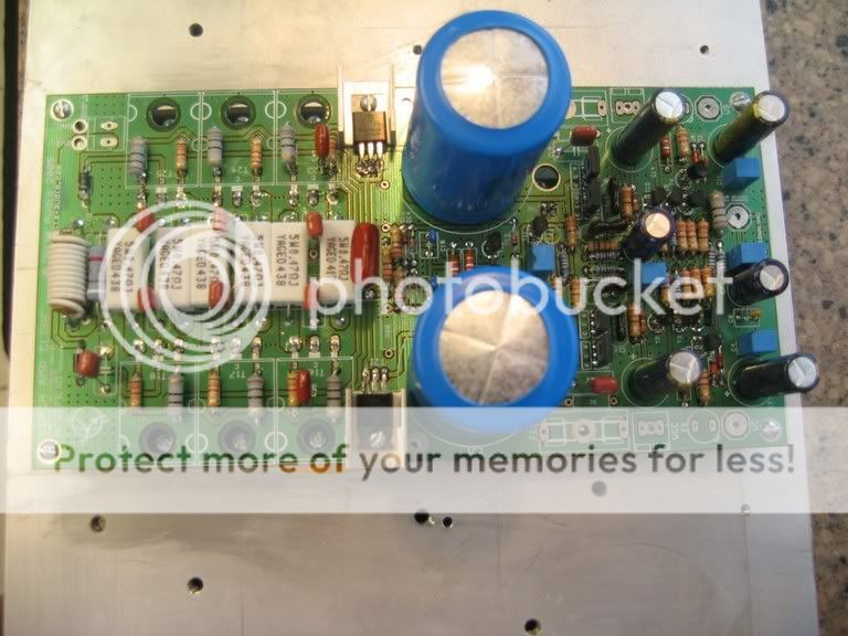
still4given said:
One more question. If you install F1 & F2 and one of them blows and not the other, what happens to the DC offset? Would the speakers be in jepoardy?
As luck would have it, I popped a rail fuse on my leach amp a couple days ago. The output stays around ground potental - maybe 30 mV extra offset.
I think F3 and F4 were to fuse the optional independent front end supply.
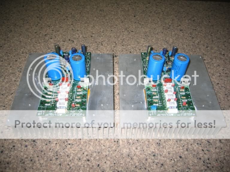
EDIT: You've got plenty of heatsnk there, Terry. Looks good.
BobEllis said:
As luck would have it, I popped a rail fuse on my leach amp a couple days ago. The output stays around ground potental - maybe 30 mV extra offset.
I think F3 and F4 were to fuse the optional independent front end supply.
EDIT: You've got plenty of heatsnk there, Terry. Looks good.
Actually, if I'm looking at the boards correctly, they are to fuse the backend when running the front end seperately. I am still hoping to build regulation for the front end and run them seperately, in which case I might use F3 and F4.
Those heatsinks were planned for the superamp that I couldn't get working. They are probably over kill for this amp.
Blessings, Terry
For a quick regulated front end, you can use a 317/337 or 1085/1033 just to get "taste" of the sound with it. Make sure you respect the ground points of the regulators. The ICs only see the voltage between the regulated and unregulated values so no need to worry about that since you have about 35 to 40 to work within.
With a good regulator it will seem like you gained an extra octave of extension. However there's less "bloom" which some ascribe to "closed in " sound. Personally, my preference is regulation. The dynamics are immediately recognizable and the pace timing "blah blah" stuff is real and was also discovered by my wife who has NO interest in good sound but commented on it. She complains I have too many amps and speakers so there must be something to her comment.
With a good regulator it will seem like you gained an extra octave of extension. However there's less "bloom" which some ascribe to "closed in " sound. Personally, my preference is regulation. The dynamics are immediately recognizable and the pace timing "blah blah" stuff is real and was also discovered by my wife who has NO interest in good sound but commented on it. She complains I have too many amps and speakers so there must be something to her comment.
F3,4 vertical fuses
Hi,
my www.rapidelectronics.co.uk catalogue shows a vertical fuse and a PCB fuse holder for 5.08mm (0.2inch) pitch.
Holder 9.5mm diam by 3mm high, fuses 8.5mm diam by 8.45mm high. Fuses available in T or F ratings 50mA to 5A.
They also sell resistor kit and Maplin do similar.
Hi,
my www.rapidelectronics.co.uk catalogue shows a vertical fuse and a PCB fuse holder for 5.08mm (0.2inch) pitch.
Holder 9.5mm diam by 3mm high, fuses 8.5mm diam by 8.45mm high. Fuses available in T or F ratings 50mA to 5A.
They also sell resistor kit and Maplin do similar.
Terry,
Boards look good! But you might want to reduce the length of the pins on those caps in the output stage... big risk of blowing fuses as any short curcuit between the cap pins will short the rails to ground!!!!
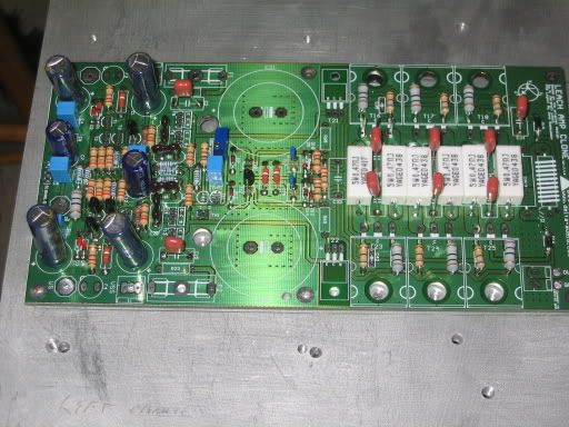
It looks like Tony may have the information you are looking for, as he has mounted the protection circuit resistors on his boards...
I have now setup my new shop (except for a smaller issue with power phone and internet) I think I will be very happy in my new home. (The shop is located in a seperate building so now amp and speaker testing can be done without dirsturbing Janni 🙂🙂🙂)
\Jens
Boards look good! But you might want to reduce the length of the pins on those caps in the output stage... big risk of blowing fuses as any short curcuit between the cap pins will short the rails to ground!!!!
It looks like Tony may have the information you are looking for, as he has mounted the protection circuit resistors on his boards...
I have now setup my new shop (except for a smaller issue with power phone and internet) I think I will be very happy in my new home. (The shop is located in a seperate building so now amp and speaker testing can be done without dirsturbing Janni 🙂🙂🙂)
\Jens
What happend, if blow only one fuse, Terry ? Got bless your bass speaker, their membrane you find on oposite wall 😀 ...
Hi Terry,
your heatsinks when oriented vertically will leave the input end of the PCB at the top of your case (stereo?). How about RCAs or XLRs fitted into the top instead of the sides? Then the cables from & to the ancilliaries will just rise up to the adjacent equipment. The output transistors will cool better if they are slightly below the middle of the sink, so do not be tempted to turn the sink upside down. Your driver sinks are a tight fit!
Your case will only need two more sides. To make building and future maintenance easier make a frame to hold the panels in place and then any or all the panels can be removed at any time. The floor panel could also be demountable if the transformer is hung from a strap bridging between the sinks, this may reduce some mechanical noise getting into the case. It might make maintenance safer if ALL the mains connections were only accessible from the bottom as well.
BUT it is really important that any demountable metal panels EACH have a permanent earth lead back to the mains safety earth point.
If and when you go regulated front end, then piggyback the small reg PSU PCB above the input end of the main PCB and arrange the interconnections to just drop straight between the respective boards. Keeps all the leads short. Or bring all the leads to an edge so that the reg PSU can be folded sideways for access to underside and to the main board.
Terry, you should take the time to read Leach's web site and FAQs. Maybe even print the site out to have the info handy. Many of your questions are answered there:
Does the amplifier put out a dc voltage on the loudspeaker if one of the power supply fuses blow?
No. If a power supply fuse blows, the amp goes dead and the output voltage is zero.
Does the amplifier put out a dc voltage on the loudspeaker if one of the power supply fuses blow?
No. If a power supply fuse blows, the amp goes dead and the output voltage is zero.
- Status
- Not open for further replies.
- Home
- Amplifiers
- Solid State
- Smaller Leach Amp V1