Upupa Epops said:What happend, if blow only one fuse, Terry ? Got bless your bass speaker, their membrane you find on oposite wall 😀 ...
Nope, there will be no DC on output even with only one rail voltage. 😀
\Jens
Hi Terry,
just noticed you lifted C22 to C30 up from the heat of the emitter resistors, nice touch. Following on from Jens advice, how about resoldering all the other caps much closer to the PCB? More like a corgi than a wolfhound. Snip off all protruding wires as close to the PCB as your snips will allow.
just noticed you lifted C22 to C30 up from the heat of the emitter resistors, nice touch. Following on from Jens advice, how about resoldering all the other caps much closer to the PCB? More like a corgi than a wolfhound. Snip off all protruding wires as close to the PCB as your snips will allow.
Upupa Epops said:And if some transistor is broken ? 😉
Then you might want some sort of DC protection circuit.
There was no room left on the PCB for a relay and other parts for this, there are however lots of nice DC protection circuits floating around on this forum.
I know you have DC protection on board on some of your amps, but as different people will want different relays I think it would have been near impossible to agree on what to put on this PCB.
\Jens
Crow bar protection for Vrail?
Hi all,
last time I asked I got agreement in principle but no design ideas.
How do you get SCR (orTriac) triggering to crow bar the PSU rails if one Vrail drops out?
This needs to be fairly quick so that after one Vrail falls to low volts either due to fuse blowing or shorted output transistor the speaker load will see only a short term DC. The other Vrail will fuse due to crow bar action after the on board line fuse. If the first fuse has not yet blown the opposing SCR trigger will now see zero volts on the crow barred Vrail and blow the first Vrail in sympathy.
I suspect the detector and trigger are quite simple.
Let's have some ideas.
Then you might want some sort of DC protection circuit.
i am not taking chances, i will add a speaker prtector based on the upc1237 ic, will post pics and schems once made.
Are not so many relais on the market, which are suitable for DC protection, Jens. I notice, that relais which I was using in my first generation of amps wasn't good for this application, 'cos they have too low DC breakability. Now I'm using 30 A relais from Nais or Finder and results are satisfactory.
Nice Find Tony
Hey - Nice find Tony. That should make things quite simple. Looking forward to seeing what you create. I think it may save some of use some expensive speakers 😀
I have a question regarding regulation. The main reason I assume that an amp may sound more rythmic is that the front ends voltage has less chance of drooping.
1. Has anybody ever tried simply running the rails higher from a separate power supply? Since the frontend draws little current - surely this would provide a similar effect - unless of course my thinking on why it sounds better is incorrect.
2. I would imagine that having 2 seperate supplies running have grounding issues. Any comments on this?
Upopa - When you refer to "DC Breakablility" are you refering to arcing?
Rod Elliot state
It has been brought to my attention that the DC arc can (and does) destroy even 10A relays under some circumstances. To provide greater speaker protection, the relay wiring in Figure 2 has been modified to short the speaker to earth in case of a fault. This way, even if the contacts do arc it will be directly to earth. This is much safer (for the speakers), and the arc to earth will blow the fuse a lot faster than if an 8 ohm load is a part of the circuit. It is strongly recommended that this new scheme is used as a matter of course. It is worth noting that any DC protection system that does not use this method will almost certainly fail to protect the speakers with a medium to high powered amplifier.
grounding
Hi Byrd,
run all your PSU and decoupling grounds back to the same power ground. No problem.
Hi Byrd,
run all your PSU and decoupling grounds back to the same power ground. No problem.
Upupa Epops said:And if some transistor is broken ? 😉
I made this with uPC1237 ( PCB and shematic made Zoran from www.audiofil.net ), Its very simple,iuPC1237 have muting function when the power supply is turned ON or OFF and protect speakers from DC,I have two relay for one speaker in parallel,...
Attachments
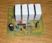
JensRasmussen said:Terry,
Boards look good! But you might want to reduce the length of the pins on those caps in the output stage... big risk of blowing fuses as any short curcuit between the cap pins will short the rails to ground!!!!
\Jens
Yes, you should always reduce lead length of RF bypass caps to a minimum. Also, choose low inductance caps for this application to reduce the chance of oscillation. Wound caps, i.e., polystyrene, etc., supposedly great for their low DA, etc., tend to be more inductive because they are wound. Ceramic NPO are low inductance, and are almost a perfect capacitor, and a small. Small is another indicator of low inductance. Although the typical ceramic have a deservedly bad reputation, the NPO versions are excellent. They excell at all capacitor properties. However, I have been unable to find out how microphonic they are. Regular ceramics are quite bad in this regard.
Again, Leach's site discusses the problem of inductance surrounding the caps in the bypass applications:
Leach power supply
With Jens' boards, the inductance of the leads should be smaller because the large PS caps are mounted on board, lessening the lead length. However, it is good practice to reduce inductance issues as much as possible.
As a footnote to prior post, you should look for stacked capacitors if going the poly film route. Stacking minimizes the inductance.
pooge said:
Although the typical ceramic have a deservedly bad reputation, the NPO versions are excellent. They excell at all capacitor properties. However, I have been unable to find out how microphonic they are. Regular ceramics are quite bad in this regard.
I only use ceramic caps at work. They are excelent because they have very low ESR and ESL. They are however very nonlinear as their value changes a lot depending on what voltage is applied to them.
I use some 100uF 6.3V for a 3.3V supply, at 3.3V their value has dropped to some 60uF - this at room temperature. It gets even more interresting if the temperature falls or rises.....
Don't be tempted to use ceramics for the Cdom in the VAS!
\Jens
pooge said:
Yes, you should always reduce lead length of RF bypass caps to a minimum. Also, choose low inductance caps for this application to reduce the chance of oscillation. Wound caps, i.e., polystyrene, etc., supposedly great for their low DA, etc., tend to be more inductive because they are wound. Ceramic NPO are low inductance, and are almost a perfect capacitor, and a small. Small is another indicator of low inductance. Although the typical ceramic have a deservedly bad reputation, the NPO versions are excellent. They excell at all capacitor properties. However, I have been unable to find out how microphonic they are. Regular ceramics are quite bad in this regard.
Again, Leach's site discusses the problem of inductance surrounding the caps in the bypass applications:
Leach power supply
With Jens' boards, the inductance of the leads should be smaller because the large PS caps are mounted on board, lessening the lead length. However, it is good practice to reduce inductance issues as much as possible.
Hi pooge,
I can easily reduce the length of the caps but are you telling me that the ones I used are no good for this application? I don't recall ceramics being called out in the BOM. Things like this should be said before us folks go out and buy and install parts IMHO.
One thing I have found is that the through plated holes, while very nice, are a pain in the rear end when it comes to replacing parts. It is very difficult to remove all of the solder from them.
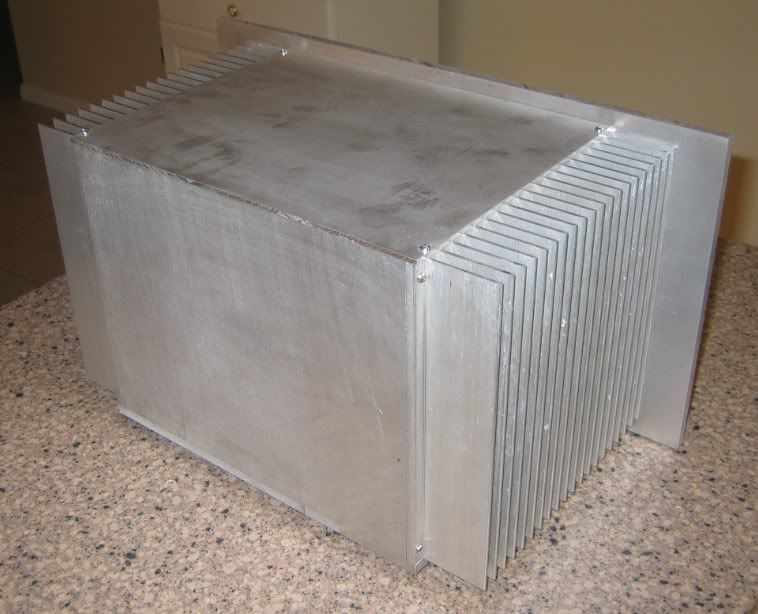
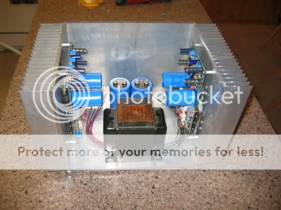
I have a few pics of my case. It has not been drilled for jacks but it will give an idea of what direction I am heading.
I am not sure, but I think I read that an E-core transformer need to be turned in a certain direction due to it's magnetic field. If someone knows please instruct me before I bolt this one in.
Thanks
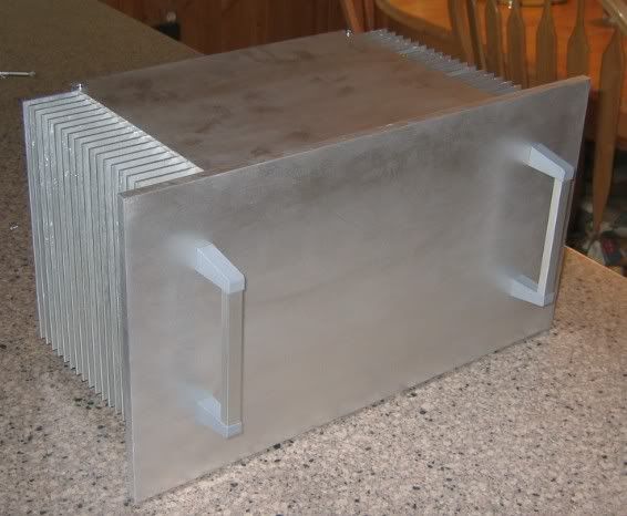
One friendly advice : make corners at heatsink round - try to take it in your arms and you will feel, whatabout I'm talking 😉 .
Member
Joined 2002
Upupa Epops said:One friendly advice : make corners at heatsink round - try to take it in your arms and you will feel, whatabout I'm talking 😉 .
OH COMMON!!! you dont like metal dent's i your arms with blood 😀 i do agree with his post.
I say leave those corners exactly as they are. Good Anti-Thief Devices.
When you leave your house - remove the handles 😉 . Let em try steal that behemoth then
When you leave your house - remove the handles 😉 . Let em try steal that behemoth then
Hi Terry,
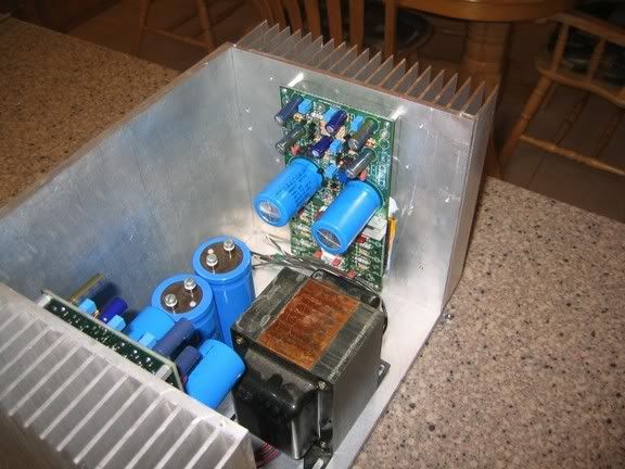
I hope you are going full monoblock with the PSU. The two smoothing caps look suspiciously like a stereo setup.
I have some protection numbers for you.
First my assumptions.
3 pairs 2sa4281
Tc <=35degC.
Re = 0r68
Vbe = 650mV (Tr10,12)
Vrail=65V when driving max power into 8R load.
Are these correct?
protection values based on the above conditions:-
R41 = 1k2
R68 = 15k
R28 = 100r
R30 = 6k8
These give a provisional short circuit current, Isc = 6A8
and peak current into 2r at max output of 55Vpk, Ipk = 27A5 when Vbe=650mV. I am awaiting feedback on a test method to allow R28 to be trimmed to achieve these values and thus be condident that the devices stay inside the derated SOAR. BTW I think the protection circuit would benefit from a large increase in C17,18 to within the range 100nF to 22uF. This is to allow short term peak currents to pass through to the load without the protection cutting in when not needed.
However this combination of Vrail and 3 plastic pairs is struggling to drive a reactive load and stay inside the SOAR for Tc=35degC
Max loading is 8ohms 58 degree phase angle (any normal speaker load).
4ohms 34 degree phase angle (easy speaker load only).
Member
Joined 2002
I was just about to post something like that. i thought that black iron core transformer was just there for looks is it ? Id say thats a little small for a stereo amplifier setup.
Hi Terry,
your pics downloaded while I was writing that last part.
My comments;-
Demountable panels and floor for maintenance access.
Transformer hung from a strap between heatsinks.
Transformer seems a bit small, what is the VA rating?
Earth straps to all demountable metal panels.
These are a repeat but you are not listening.
Once you start filling up the inside with soft start, cables, rectifiers, front end PSUs (4 of them) etc., many components are going be be buried deep inside.
- Status
- Not open for further replies.
- Home
- Amplifiers
- Solid State
- Smaller Leach Amp V1