bowdown said:Thanx Bob for your information. Can i use IRF640/9640 instead? and if i want ot regulate the whole amp how many i will need. How many amps is each complimentary pair capable of? that way i can just see how much current i need and just parallel more fets together. That way if i ever need it for a differnt circuit i can just calculte how many pairs i will need. Also if possible how can i work out heatsink size for the fets?
Regard
Bowdown
I don't see why you couldn't use the irf640/0640. The current available depends on how much voltage you are dropping across the regulators and their heat sink. Assuming 10 volts across the regulator, a 30 C heat sink and a goal of keeping the junction temperature under 100C, you should be able to get 3A out of each.
High current regulators have been discussed at length in other threads, such as the Leach superamp redesign thread. With mosfets you can simply parallel as many devices as you need. With bipolars you may be able to reduce the waste heat, but the design becomes more complex.
Heat sink calculations are pretty straight forward:
Decide what your heat sink temperature is going to be.
subtract it from 100 (the design junction temperature) to get the design junction temperature rise
Add up the themal resistances from junction to the heat sink: junction to case (from datasheet), across the isolator (I measured about 1.3 C/W for pink silpads) and mounting device to heat sink (are you using an L-bracket or some sort of heat spreader?)
Divide the temperature rise by the thermal resistance to get the allowable power per device.
multiply the power per device by the number of devices.
Heat sink temperature rise = Power * K, rearranging to solve for K, divide heat sink temperature rise (sink temp-ambient temp) by the total power dissipation. this is the total K required. Multiple sinks add like parrallel resistors - two .5 C/W sinks will give you the equivalent of a .25C/W sink.
Using our example above, 20C ambient, 30 C heat sink, goal of 6 amps regulated output (good for one channel) and 10V across the regulators:
100-30= 70C junction temp rise
thermal resistances = 2.3 Rjc=1.0, Rcase-sink=1.3
allowable power per device 30 W (rounded)
30 Watts / 10 Volts dropped =3 A per device, so two required to meet output goal of 6A.
total regulator dissipation = 60 W (burning all of the time, worst at idle. The Leach amp idles at around 15 W.)
Heat sink - ambient = 10 degrees
K required = 10/60 = .17 - one healthy heat sink. Time to go back and redo the calculations allowing 20-30C heat sink temperature rise and see A) how much smaller the heat sinks can be and B) how many more devices you'll need.
TO-247 devices have lower junction to case thermal resistance, so you may be able to use fewer of them. Kapton and aluminum oxide isolators have lower thermal resistance as well. Mica is a hair better than silpads.
Loboone:
Anything that gives you 50-60 volts +/- will be fine. 300 VA per channel is plenty. For unregulated main rails 40-0-40 will get you around 60 volt rails. bump it up 5-10 volts to feed the regulators. I suggest that you not regulate the output stage, unless you like lots of heat (and you might get better results going to a class A design since you're going to to need the same heat sinks).
You could regulate half a dozen or more front ends with a 160VA transformer.
BobEllis, the statement about not regulating the ouputs unless you like lots of heat needs to be qualified. I have both a LOW TIM3 and a Leach Superamp that are both fully regulated and the power supply heatsinks are barely warm under "normal" operating conditions. If you build it to test with a contnuous load, you will generate lots of heat in the regulator BUT if you use the regulator for sound quality purposes in a domestic setting the average current is quite reasonable. The heat can be further reduced by using a stiff transformer that does not droop too much under load. That way the amount of voltage that must be reduced between off and on load is very small and this can be taken advantage of.
Here's a pic of the Leach Low TIM3 amp.
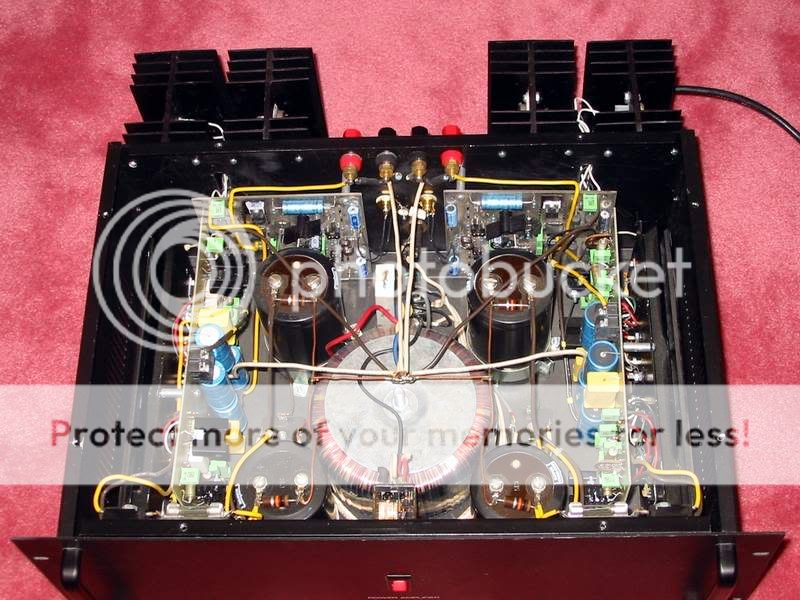
It uses a 750VA transformer feeding 4x40,000UF power supply caps. There are two separate regulators on each side for left and right channels. The power to the amp board is supplied via two wires for each rail. One is a heavy current/ouput feed and the other is the low current/front end feed. The heatsinks are barely warm to the touch and the regulators are "cool" under normal listening conditions. Even when listening at brisk levels with some 87db/W B&Ws the regulator heatsinks barely get warm.
Even when pushed in a commercial setting, when I had these driving a pair of VMPS Larger Subs (4 ohms) for a party of 200 the heatsinks were just slightly warm.
As you can see the amount of extra resources for the regulators can be high.
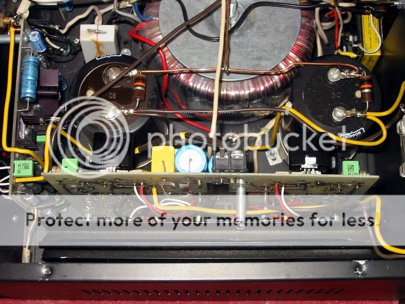
Here's a pic of the Leach Low TIM3 amp.
It uses a 750VA transformer feeding 4x40,000UF power supply caps. There are two separate regulators on each side for left and right channels. The power to the amp board is supplied via two wires for each rail. One is a heavy current/ouput feed and the other is the low current/front end feed. The heatsinks are barely warm to the touch and the regulators are "cool" under normal listening conditions. Even when listening at brisk levels with some 87db/W B&Ws the regulator heatsinks barely get warm.
Even when pushed in a commercial setting, when I had these driving a pair of VMPS Larger Subs (4 ohms) for a party of 200 the heatsinks were just slightly warm.
As you can see the amount of extra resources for the regulators can be high.
Point taken - Working the worst case scenario, I simply forgot that the regs don't dissipate the full heat until max current is drawn. If you want to be able to produce maximum power continuously you'll need massive sinks, but you can certainly get away with less in a reasonable domestic setting (excluding party duty).
I have four channels of Leach amp on an Apex Jr tunnel, mounted horizontally. I intended to make a thermal switch to turn the fan on if needed, but never got around to it since they barely get warm at what I consider too loud conditions. That was with two channels bridged driving my sub and the others driving the mains. Since the amp is now used biamping my bedroom speakers, I'll never need the fan.
I have four channels of Leach amp on an Apex Jr tunnel, mounted horizontally. I intended to make a thermal switch to turn the fan on if needed, but never got around to it since they barely get warm at what I consider too loud conditions. That was with two channels bridged driving my sub and the others driving the mains. Since the amp is now used biamping my bedroom speakers, I'll never need the fan.
I'm wondering about the two Pass regulators. The one for the Zen vs the A75. The regulator portion for the A75 looks a bit simpler that the SOZ.
If the one for the A75 is as good or better, then maybe someone who is good with Eagle or the like, could make a foil pattern for just the regulator portion. I have Eagle but don't understand it well enough yet to tackle this. There are only 22 componants. I suppose I could try to bread-board it, but there may be enough interest in a regulator for this amp to make it worth while designing a PCB for it. Especially since Jens designed the board to be split if desired.
Blessings, Terry
Re: piture updates!
Hi Tony,
Would you mind telling me what you used for the emitter resistors? I'm having trouble finding resistors that will fit.
Thanks, Terry
Tony said:completed boards:
An externally hosted image should be here but it was not working when we last tested it.
one board with thermal compensating diodes:
An externally hosted image should be here but it was not working when we last tested it.
Hi Tony,
Would you mind telling me what you used for the emitter resistors? I'm having trouble finding resistors that will fit.
Thanks, Terry
Would you mind telling me what you used for the emitter resistors? I'm having trouble finding resistors that will fit.
hi Terry,
those are "dale" 0.3ohms 5% 7watters, picked them up from a 'surplus' store years ago, one lot with about 200pcs and was saving them for these kind of projects....
Re: Re: piture updates!
The Mills 5W, non-inductive, 1% wirewounds ought to fit. They are available from Michael Percy Audio, Parts Connexion, and others.
I should be receiving mine any day now. I'll let you know if they fit.
still4given said:
Hi Tony,
Would you mind telling me what you used for the emitter resistors? I'm having trouble finding resistors that will fit.
Thanks, Terry
The Mills 5W, non-inductive, 1% wirewounds ought to fit. They are available from Michael Percy Audio, Parts Connexion, and others.
I should be receiving mine any day now. I'll let you know if they fit.
Terry-
What's the distance between pads (don't have my boards handy). I am looking at the datasheet for Vishay/Dale LVR resistors from Mouser.
http://www.vishay.com/docs/30206/lvr.pdf
and mouser cat page: http://www.mouser.com/catalog/623/459.pdf
They are .925in long (5W) and low inductance.
What's the distance between pads (don't have my boards handy). I am looking at the datasheet for Vishay/Dale LVR resistors from Mouser.
http://www.vishay.com/docs/30206/lvr.pdf
and mouser cat page: http://www.mouser.com/catalog/623/459.pdf
They are .925in long (5W) and low inductance.

I measure 29.5 mm lead spacing, and 8 mm width allowed.
Although not a non inductive part, the Vishay/Dale RS005 series fits barely 7.92mm nominal diameter (mouser P/N 71-RS5-0.33 or 71-RS5-0.5)
Although not a non inductive part, the Vishay/Dale RS005 series fits barely 7.92mm nominal diameter (mouser P/N 71-RS5-0.33 or 71-RS5-0.5)
Just to note, the LVRs are approx 8.25mm, which sounds just a bit too wide.
Although they are pricey, the Phoenix AC05 (5W) and AC07 (7W) ww's will fit:
http://dkc3.digikey.com/PDF/T052/1076.pdf
Although they are pricey, the Phoenix AC05 (5W) and AC07 (7W) ww's will fit:
http://dkc3.digikey.com/PDF/T052/1076.pdf
Looking at it again, Mouser lists a non inductive 5W part - 71-NS5-0.50, but no stock and minimum of 100 pieces. 🙁
the 71-RS2B-0.3 or 0.5 is smaller (allows room for air circulation and rated 3 W continuous and 15W for 5 seconds. The only non-inductive equivalents that Mouse lists have lug terminals.
So how important are non inductive resistors? How much inductance do they have (not on the data sheets I've seen) and does it really matter when they are inside the feedback loop? I used plain old inductive cement emitter resistors in my originalleach amps and they sound fine.
Don't know about the importance of non-inductive here, but it can't hurt. This is where the protection circuit senses the output current via the voltage across these resistors. I think a tight tolerance of 1% or better could better control current sharing in the output transistors, assuming the transistors are matched.
The inductance block instantaneous current demand and will create
a small voltage variation according on L di/dt. In high current applications, you try to minimize this behavior. The effect on the feedback loop is bandwidth dependant, you do not want to propagate this feedback at the input or at least make sure the bandwidth is low enough to filter the glitch.
My 2 cents...
that makes sense, but has anyone measure the inductance of low value wirewounds to see if it amounts to anything that would have any effect below, say, 200 Khz?
I suspect that the bandwidth of the amp itself is limited long before the inductance of a wirewound resistor has any noticeable effect. (Flame suit on.)
I suspect that the bandwidth of the amp itself is limited long before the inductance of a wirewound resistor has any noticeable effect. (Flame suit on.)
Bob - I have to agree with you.
The resistors that Leach specified are standard 5 Watt wirewounds (5%).
Although everything said is technically correct - in practice I doubt it would be the cause of performance problems in the amp as otherwise Leach would have picked this up himself and surely commented in his writings on the amp.
jean.ricard said:The inductance block instantaneous current demand and will create
a small voltage variation according on L di/dt.
Can i rewrite it as this:
L * di/dt = L * [di/dV * dV/dt]
- Status
- Not open for further replies.
- Home
- Amplifiers
- Solid State
- Smaller Leach Amp V1