The race is on - who's going to be the first to power up 😉. Just be wary of Puff the magic dragon.
You are keeping us in suspense - how does it sound?
If there is anybody in South Africa who missed the group buy and wants a board or 2 let me know. I am going to do a couple for myself. They ARE more expensive that the groupbuy boards - but hey - what can you do.
I am also sourcing all parts - so if you are wanting to get in on the action you can mail me through the forum or you can contact the suppliers directly yourselves
I have attached an excel spreadsheet of my expected costs so far.
Attachments
Hi guys,
I wanted to post a pic of the schematic for the Hafler XL-280 PSU. I'm wondering if this would work for the Leach.
Here's the pic.
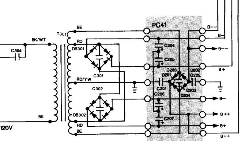
B+ and B- are 65VDC while B++ and B-- is 75VDC. C204, C205, C207 & C208 are 10,000mfd, 75VDC and C201 & C203 are 470mfd, 100v.
I guess I'm asking if the front end can be run at 75V rails without regulation. I'm not sure I'm up to trying to work out the regulation.
Thanks, Terry
I wanted to post a pic of the schematic for the Hafler XL-280 PSU. I'm wondering if this would work for the Leach.
Here's the pic.
B+ and B- are 65VDC while B++ and B-- is 75VDC. C204, C205, C207 & C208 are 10,000mfd, 75VDC and C201 & C203 are 470mfd, 100v.
I guess I'm asking if the front end can be run at 75V rails without regulation. I'm not sure I'm up to trying to work out the regulation.
Thanks, Terry
I would not run the front end that high. In fact, I'm not sure I would run the front end any higher than the output stage. You want the front end to clip before the output stage. If you run it at higher voltage, the output stage may clip first and "stick". It takes longer for the output stage to recover from a clip than the input stage.
Also take a look at the diode that is between the two rails on the circuit board. What is the reasoning behind that?
C'mon Terry, after all the amps you've built and successfully troubleshot, you're shying away from a stinkin' regulator? 😉
A simpler regulator is in the balanzed zen preamp article at the passdiy link I gave you earlier. Substitute a 12 volt zener for ONE of the 9.1 volt ones in the reference string and you've got 63 volts. Substitute 2 12 volt zeners in there and you have 66 volts. this regulator is simple enough to build on perfboard, as well.
If you are dead set against regulators, you can run the front end that high, with Pooge's caveat about clipping, adjusting R3 and R22 to suit.
Or you can use a CRC or CRCRC filter to drop the voltage. Instead of the low resistance Rs you used in your Krell output stage, use around 500 ohms total. A 1 watt resistor ought to do, but check the dissipation is no more than half its rating. To calculate the actual resistance needed, use ohm's law - divide the volts to be dropped by the current drawn (in Amps) I don't remember the draw of the front end, but I think it is somewhere around 30 mA, hence my 500R suggestion. Someone may have the actual draw, or you can measure it once you have it built.
BobEllis said:C'mon Terry, after all the amps you've built and successfully troubleshot, you're shying away from a stinkin' regulator? 😉
A simpler regulator is in the balanzed zen preamp article at the passdiy link I gave you earlier. Substitute a 12 volt zener for ONE of the 9.1 volt ones in the reference string and you've got 63 volts. Substitute 2 12 volt zeners in there and you have 66 volts. this regulator is simple enough to build on perfboard, as well.
If you are dead set against regulators, you can run the front end that high, with Pooge's caveat about clipping, adjusting R3 and R22 to suit.
Or you can use a CRC or CRCRC filter to drop the voltage. Instead of the low resistance Rs you used in your Krell output stage, use around 500 ohms total. A 1 watt resistor ought to do, but check the dissipation is no more than half its rating. To calculate the actual resistance needed, use ohm's law - divide the volts to be dropped by the current drawn (in Amps) I don't remember the draw of the front end, but I think it is somewhere around 30 mA, hence my 500R suggestion. Someone may have the actual draw, or you can measure it once you have it built.
I don't want to shy away from it. I can't find the schematic fo rthe regulater. I guess my search abilities aren't what they should be. I'll keep seraching. I would like to learn how this works and since I have a transformer theat lends itself to it this would be a good time to learn. If you can find a link to what I need I would gratly apprecieate it.
Blessings, Terry
Pass regulator link
Terry,
Mr. Pass's article on active supply regulation. Same as used in Balanced Line Stage etc.
http://www.passdiy.com/projects/zenv3-1.htm
Terry,
Mr. Pass's article on active supply regulation. Same as used in Balanced Line Stage etc.
http://www.passdiy.com/projects/zenv3-1.htm
piture updates!
completed boards:
one board with thermal compensating diodes:
power supply modules with front-end regulator board:
completed boards:
An externally hosted image should be here but it was not working when we last tested it.
one board with thermal compensating diodes:
An externally hosted image should be here but it was not working when we last tested it.
power supply modules with front-end regulator board:
An externally hosted image should be here but it was not working when we last tested it.
An externally hosted image should be here but it was not working when we last tested it.
An externally hosted image should be here but it was not working when we last tested it.
An externally hosted image should be here but it was not working when we last tested it.
Also - would it be possible for you to make your schematics and PCB layouts for that regulator available to those monitoring this thread
OK, I found this thread.
Is this the regulator that you guys are talking about?

If so, are there some values that would need to be changed to accommodate the voltage from my transformer?
Thanks, Terry
Is this the regulator that you guys are talking about?
An externally hosted image should be here but it was not working when we last tested it.
An externally hosted image should be here but it was not working when we last tested it.
An externally hosted image should be here but it was not working when we last tested it.
If so, are there some values that would need to be changed to accommodate the voltage from my transformer?
Thanks, Terry
That's the one Terry.
For your purposes, you don't need the voltage doubler, so only use the part below the "38V unreg" You'll connect your bridge rectifiers' +/-outputs to the spot where D2 and D4 connect respectively- convenienly jumpers on the board, so it is easy to see where you can cut the design. You'll need to make a spot for C6 and C7, though.
Change Z1 and Z2 to 12 volts, upgrade the caps to 100V and you're done. C8 and C9 will probably end up being a bit too big for their designated space so you can either move the ground trace a little to suit or just have the caps stand up a bit and insulate their leads. Use a decent size heat sink on Q2 and Q3, since they will be dissipating over half a watt. The thermalloy 6106 recommended in the article is barely sufficient.
You don't need R15, R16 and LED1, but is is a convenient spot to run a pilot light. Use 1W resistors, asnd mount them up off the board to allow some airflow - the original ran those 1/4W resistors at .23W, and at 65 volt rails, you have about .8W total. I used 25 or 30K total to get my blue LED brightness down to a reasonable level.
Likewise, you don't need R18, R19 and Q1 unless you want to use a fan. Caution - the board layout has R18 connected to the emitter of Q1, so you need to drill a hole in the base trace and make the connection there unless you want to run your fan at full rail voltage. (screaming fan, poof! acrid smoke, missed that first time around) The values noted are for a 24 volt fan, for 12V drop R18 to around 2.7K and fiddle with R19 to get the speed you desire.
Terry,
unlike many CBS artists, Mr. Pass has a fun and very comprehensable way of explaining things.
At least, that's my opinion, the stuff electronics people write in my lingo i need to read again a couple of times before the brick hits me from behind.
Read some of the maestro's stuff, including this one of the voltage doubler/regulator.
Byrd said:Tony - what voltage are you going to be running the front end on?
power amp rails are +/-50volts, front-end rails will be +/-52 to 55volts....
schematic.

choice of components were based on on-hand parts.
bowdown said:Hey guys i was just wandering if it is possible to use this circuit from pass labs and modify it using the right zener combination??
Regards
Bowdown
Yes, no problem. Choose a zener string totaling about 4V more than your desired output voltage. You will be able to use a single IRF610/9610 if you are just regulating the front end.
If you intend to regulate the whole thing, then watch the dissipation and SOA of the regulator pass devices - you may want to parallel three or more. Your unregulated voltage should be high enough that it doesn't sag to less than 5V (including ripple)above the regulated rail voltage under max load.
Thanx Bob for your information. Can i use IRF640/9640 instead? and if i want ot regulate the whole amp how many i will need. How many amps is each complimentary pair capable of? that way i can just see how much current i need and just parallel more fets together. That way if i ever need it for a differnt circuit i can just calculte how many pairs i will need. Also if possible how can i work out heatsink size for the fets?
Regard
Bowdown
Regard
Bowdown
Can someone pls post a link explaining advantages/disadvantages of using and (not using) regulated front-end/outputs.
I recall this question has been answered in one of Leach's pages:
My apology for a silly question... just to clear my doubt.
roland
"everybody was a lamer, before they become ELITE" - Code viRUS
I recall this question has been answered in one of Leach's pages:
Can I use a regulated power supply with the amplifier?
Yes. I have had one student who used regulated power supplies because the bargain transformer that he bought had too high a secondary voltage rating. He designed regulators to drop the voltage down to the required values. I have no recommendations on the design of the regulators. They must be able to pass the full amplifier current and the pass transistors in them must be heat sinked. In effect, each regulator is another power amplifier that supplies voltage and current to the amplifier.
My apology for a silly question... just to clear my doubt.
roland
"everybody was a lamer, before they become ELITE" - Code viRUS
"In the X150, additional voltage for the front end is derived from separate windings on the main
transformers. This extra front end supply lowers the distortion and noise of the system, and
allows the front end to swing the output stage rail-to-rail with losses on the order of only a volt
or so, extracting every last possible watt."
http://www.passlabs.com/downloads/x150_om.pdf
transformers. This extra front end supply lowers the distortion and noise of the system, and
allows the front end to swing the output stage rail-to-rail with losses on the order of only a volt
or so, extracting every last possible watt."
http://www.passlabs.com/downloads/x150_om.pdf
Re PSU for leach6
I have been watching this tread and am wondering if I used this circuit for the regulated supplies (x2 per channel), one for front end and other for output would it work? What supply rails would anyone sujest?
Would 300va toroidals do the trick or could I get away with 160VA for the front end and 300VA for the output?
http://www.tcaas.btinternet.co.uk/jlhnewps.htm
Keep up the good work.
Ian
- Status
- Not open for further replies.
- Home
- Amplifiers
- Solid State
- Smaller Leach Amp V1