Hi Bob,
I could just as easily use the MJL3281/1302. I have a supply of those as well. I guess I was under the assumption that the 4281/4302 were better units. I doubt I will be using this amp on stage. I have some pro amps for that purpose and My JBL Eons are powered.
I had thought about just using the values that Jens used on his 10 transistor version but I think I'll just wait until they get this all together. This is unusual, It seems like everyone is always waiting on the PCBs. This is the first time I got the PCB before the design was complete. 😀
Hi Andrew,
I'm interested in the "resistor kit" you spoke of. Where would a person buy something like that? I just sat down with my wife last night and cataloged the parts I have on hand. I filled four baggies with resistors and today as I was going over the BOM for this amp, I have almost none of the parts I need. This .6w thing makes parts hard to find. Seems like it's not a very popular wattage. Dr Leach called out 1/4W for almost all of his resistors. I want to try and follow Jens' design as much as possible since he designed the board. I'm going to measure the hole layout tonight on the boards and see where I’m limited in size for the resistors. Vishay/Dales are longer than the resistors Jens shows in his BOM. If they will fit, I may go with them instead.
Blessings, Terry
I could just as easily use the MJL3281/1302. I have a supply of those as well. I guess I was under the assumption that the 4281/4302 were better units. I doubt I will be using this amp on stage. I have some pro amps for that purpose and My JBL Eons are powered.
I had thought about just using the values that Jens used on his 10 transistor version but I think I'll just wait until they get this all together. This is unusual, It seems like everyone is always waiting on the PCBs. This is the first time I got the PCB before the design was complete. 😀
Hi Andrew,
I'm interested in the "resistor kit" you spoke of. Where would a person buy something like that? I just sat down with my wife last night and cataloged the parts I have on hand. I filled four baggies with resistors and today as I was going over the BOM for this amp, I have almost none of the parts I need.
This .6w thing makes parts hard to find. Seems like it's not a very popular wattage. Dr Leach called out 1/4W for almost all of his resistors. I want to try and follow Jens' design as much as possible since he designed the board. I'm going to measure the hole layout tonight on the boards and see where I’m limited in size for the resistors. Vishay/Dales are longer than the resistors Jens shows in his BOM. If they will fit, I may go with them instead.Blessings, Terry
Terry,
the original devices are 250 watt MJ15003/4 devices.
Version 4.5 uses 40vac transformers, after rectifying that is about 56 vdc.
56 divided Pi ~39.5 vac
250 watts per device divided by 39.5 ~6.3 amps.
The protection will activate if there is around 0.6 volts across R28 or R29, original Leach circuit.
With R28=270 Ohms, R37/R39 =680 Ohms, there should be around 2.1 volts across the emitter resistors.
With these chosen as 0.33 Ohms by Mr Leach the max static current per device would be around 6.3 amps.
Same as above, that is when the output voltage is zero for the positive rail.
Above 0 volts on the output R30 and D5 step in, taking more current away from the base of the protection transistor the higher the output voltage becomes.
The value of R30/R31 determines how much the max current increases when output voltage increases.
As the MJL's have a higher voltage rating than the MJ's you can leave R30/R31 at 3K9.
Roughly speaking, if you are using 230 watt MJL's and 64 volt rails, the max current would be around 5 amps per device.
With the same 0.33 Ohm emitter resistors that is 1.65 volts across them.
With the same 270 Ohm value for R28/R29, the value for R37/R39/R38/R40 would become 470 or 475 Ohms.
That is without using R68/R69.
If you intend to use other emitter resistor values than 0.33 Ohms you need to re-calculate.
With 3 devices in parallel the minimum current allowed is then 15 amps.
SOA of the MJ15003/4 and MJL4302/4281 is 1 amp at 100volts for both.
I just bought 7500 BC/Philips metalfilms on the web for diddly, if you need some for R68/R69 later i'll send you some.
Hehe
Terry Thanks - I am a twit. I poked about their site and didn't see the link for purchase.
I know what you mean about being patient. The first time I built the Leach Low Tim - It was done in 3 days from start to finish (Well excluding the chassis). That was 4 channels.
That version still had the obligatory nest of wires.
Well at least I am not afraid to try this one now. I am going to be getting boards made locally here seeing as though I missed the big buy.
jacco vermeulen said:... Roughly speaking, if you are using 230 watt MJL's and 64 volt rails, the max current would be around 5 amps per device.
With the same 0.33 Ohm emitter resistors that is 1.65 volts across them.
With the same 270 Ohm value for R28/R29, the value for R37/R39/R38/R40 would become 470 or 475 Ohms.
...
Hi Jacco -
Did you arrive at 5 amps per device using max current at 0 output voltage and 100 msec? Just trying to follow along. Sounds like a bombproof solution - it should survive a dead short under any signal.
Interesting coincidence that 475 ohms for R37 is the same as Leach used in version 4.2, before increasing it to 680 after receiving complaints of the protection circuit kicking in when driving low impedance loads. I guess there is room to fudge, if we assume that the user has some sense and loads won't be a dead short or purely reactive. Unfortunately this is where my math ability comes up short.
Hi jacco,
OK, I just read through your post about 10 times. Let me see if I have this right.
Using the MJL4302/4281, 64V rails, .33ohm emitter resistors then I can leave R30/31 at 3k9. Using 270R for R28/29 then R37-R40 should be 470R or on Jens' drawing it's R41-R43 and R60-R62.
Am I on track with this?
It's OK to leave off R68/69 for now? Are we still waiting for the values for these or do you know them?
Thanks, Terry
hi,
i am using 120k on my boards for R68/R69 to give a 0.1xx volts at standby at the bases of the protection transistors, my boards have rails of +/-55volts at idle...
i am using 120k on my boards for R68/R69 to give a 0.1xx volts at standby at the bases of the protection transistors, my boards have rails of +/-55volts at idle...
Thanx everyone who tried to help me especially AndrewT.
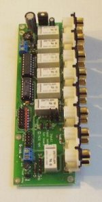
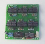
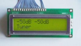
Does anyone have a good preamp circuit to go with the old and the new leach amps? also to run the leach super amp. I currently use a resistor/ relay network for volume and also have a selector board that has six inputs.
All i want to do is build the preamp into this, so i dont need volume control or inputs, just needs to be a preamp of high quality.
Any help again would be appreciated.
Regards
Bowdown
ps here are a couple of pics of what i am using.
Attachments
yeah sound good but how do i transfer what i have posted to a new thread? Can a moderator move it for me? Sorry if i wasnt supposed to post it here, just thought that heaps of people on this post have a lot of knowledge of this particular amp.
Cheers
Bowdown
Cheers
Bowdown
still4given said:Am I on track with this?
No, i am the one not on track.
I do too much head calculations, my pea brain forgot to divide the value for R37 and R39 by 2.
Let me try again:
With the setup of the Leach 4.5 Q10 and/or Q11 switch on with 0.6 volts Vbe drop.
The current doing that goes through R28 and/or R29, and comes from both R37/R39 or R38/R40 on the other side of the output.
Means the voltage drop over R37 is its value times halve the current going through R28.
Meaning (R37/2 + R28)/R28 * 0.6 is the voltage drop over one of the emitter resistors.
With R37 at 680 Ohms that is ~1.36 volts.
Divided by the 0.33 Ohm of the emitter resistor comes to 4.1 amps for each of the output devices.
That value does correspond with the graph of the protection circuit page at the homepage of Mr Leach.
With 40 vac transformers rail voltage is around 56 vdc loaded.
If you add 10 % for voltage surge rail voltage will be around 61.5 volts.
With 0 volts on the output, 61.5 vdc on the collector of the output device, and 4.1 amps emitter current, the dissipation of the output device will reach 250 watts.
As the signal is a sinus, the output devices divide the dissipation, average dissipation per device is 125 watts.
At 50 % of the max dissipation,the SOA of the device needs to be halved.
Max output current for an MJ15003/4 is 20 amps, at 50% it's 10 amps, so 4.1 amps will not kill it.
For the other part of the graph :
When the voltage on the output increases, the voltage drop from collector to emitter of the output device goes down.
As a result the output current is allowed to increase, as long as the dissipation does not go across the 50 % mark.
The maximum current allowed for an MJ15003/4 is 20 amps.
With about 18.5 amps output current for each device, the voltage drop over one of the 0.33 Ohm emitter resistors is about 6.1 volts.
With the drop of (6.1 - 0.6) volts over R37 or R39 the current going through these resistors is around 16mA.
When the protection activates 2.2 mA of that current goes through R28, the rest will flow through D5 and R30.
As R30 = 3K9 , the voltagedrop over that resistor is about 54.4 volts.
With 0.6-0.7 volts added for the diode D5, the voltage at the base of Q10 would be around 55 volts, 55.6 volts on the output.
With the 6.1 volts drop over the 0.33 Ohm emitter resistor the voltage on the emitter of the output devices is some 61.7 volts.
That is the maximum voltage to be expected from the rails, the same as at the beginning if this long post.
A stated before, i just do this by head. To get an exact approximation on currents and voltages one has to write the resistor and diode equations in something like mathcad like Jans posted and run an converging simulation.
Terry, for your values :
MJL4302/4281 are 230 watts devices, do 15 amps maximum continuous(1 sec value)
With your 64 volts transformer, the maximum you can expect is around 70 volts due to surge.
If you have all of these 70 volts drop from collector to emitter of your output devices they'll collapse if the current goes above some 3.3 amps for each device. (70 volts times 3.3 amps~230 watts)
So, at 0 volts on the output of your amplifier the total current may not become higher than 9.9 amps, assuming 3 devices in parallel.
With 0.33 Ohm emitter resistors, voltage on the emitter of the output device would be 1.08 volts max.
The combined resistor values for 3 devices would be 216 Ohms.
Times 3 makes 648 Ohms, the closest regular series value would be 620 Ohms.
620 Ohms limits the current to 3.2 amps for each output device.
For the 0.47 Ohm values on Jens part list:
0.47 Ohm times 3.3 amp = 1.55 volts.
This results in a value of 1K2 for these resistors, this limits the current to about 3.2 amps also.
In Jens's schematic these are the numbers R41/R42/R43/R60/R61/R62.
For the R30/R31 value(R26/R34 in jens's circuit):
MJL's can handle 15 amps, suppose you limit to 13.5 amps.
13.5 amps across 0.33 ~4.45 volts.
With 70 volts on the emitter of the output device, voltage after D5 would be around 65.55 volts
With the chosen value of 620 Ohms for R41/R42/R43 etc. , R30 would be around 4K.
So 3K9 would be ok for this rail voltage as well, then the limit is 13.7 amps at 70 volts on the output device emitter.
The approach of Mr Leach does not take into account that the voltage drop from collector to emitter of the output devices can be higher than the maximum rails value.
This would happen during very fast transients.
With resistor R68 between rail and the base of the protection device Q10(T10 in jens circuit), a negative voltage on the output would increase the current through R68, activating the protection at lower output currents.
For very short periods the datasheet of the MJL's shows they can do 30 amps, and this is for a square burst signal.
Very likely that for a 1mS sinus signal the max current is substantially higher.
A 1 mS signal corresponds with 500 Hz, not very likely that a 500 Hz tone can have a transient fast enough to create a Vce higher than the rails value.
Halve a phase of a 20 KHz tone lasts 0.025 mS, maybe fast enough to have Vce larger than V rails.
The question i've been waiting for is which maximum Vce value to choose for determining R68/R69.
Personally, i doubt there is a possibillity for Vce to reach as high as 2 times Vrails under "normal conditions".
On top of that there is the question if the protection circuit is able to lower the voltage on the driver fast enough to protect the output if it does happen, the only way to find out is to by trial and burn.
Wow...thanks for the posts Jacco! That's a great walkthrough of the calculations involved 🙂
The only question I have is about how you obtained the value of 216ohms...you mentioned it is the combined resistor values for 3 devices...could you elaborate this point? I see that the 1.08V is the drop over each of the emitters (in parallel), but how does that translate to 216ohms? It's probably something very simple...it seems I always try and complicate things in my mind 😉
So, at 0 volts on the output of your amplifier the total current may not become higher than 9.9 amps, assuming 3 devices in parallel. With 0.33 Ohm emitter resistors, voltage on the emitter of the output device would be 1.08 volts max. The combined resistor values for 3 devices would be 216 Ohms. Times 3 makes 648 Ohms, the closest regular series value would be 620 Ohms.
The only question I have is about how you obtained the value of 216ohms...you mentioned it is the combined resistor values for 3 devices...could you elaborate this point? I see that the 1.08V is the drop over each of the emitters (in parallel), but how does that translate to 216ohms? It's probably something very simple...it seems I always try and complicate things in my mind 😉
Hi jacco,
Thanks for doing all of this.
OK, this is a bit confusing because Jens used different numbers than Dr Leach. I am assuming that for the most part you are using the numbers from Dr Leach's schematic. Is that correct?
I'm not sure which resistors you are refering to here for the 620ohm. Are these R41-43 and R60-62? Is that why you refered to 620 as the chosen value for those? Then R26/R34 would still be 3K9?
You also stated;
So is R41 etc., 620 ohm or 1K2? I'm confused as you can see.
For some reason I have 270R written down for R29/29 ( Jens' R28/30). Now I don't know where I got that value. Is this correct?
Thanks again, Terry
Thanks for doing all of this.
OK, this is a bit confusing because Jens used different numbers than Dr Leach. I am assuming that for the most part you are using the numbers from Dr Leach's schematic. Is that correct?
So, at 0 volts on the output of your amplifier the total current may not become higher than 9.9 amps, assuming 3 devices in parallel.
With 0.33 Ohm emitter resistors, voltage on the emitter of the output device would be 1.08 volts max.
The combined resistor values for 3 devices would be 216 Ohms.
Times 3 makes 648 Ohms, the closest regular series value would be 620 Ohms.
620 Ohms limits the current to 3.2 amps for each output device.
I'm not sure which resistors you are refering to here for the 620ohm. Are these R41-43 and R60-62? Is that why you refered to 620 as the chosen value for those? Then R26/R34 would still be 3K9?
You also stated;
For the 0.47 Ohm values on Jens part list:
0.47 Ohm times 3.3 amp = 1.55 volts.
This results in a value of 1K2 for these resistors, this limits the current to about 3.2 amps also.
In Jens's schematic these are the numbers R41/R42/R43/R60/R61/R62.
So is R41 etc., 620 ohm or 1K2? I'm confused as you can see.
For some reason I have 270R written down for R29/29 ( Jens' R28/30). Now I don't know where I got that value. Is this correct?
Thanks again, Terry
ble0t said:The only question I have is about how you obtained the value of 216ohms...
Jens's circuit:
The combined current from R41, R42 and R43 goes through R28.
That is when the voltage is on the base of T10 is just below the value when the diode D5 starts to open.
T10 opens when it has 0.6 volts more on its base than on its emitter, the output.
When there is 1.08 volts over R46 to R54, and 0.6 volts across R28, then there is 0.48 volts across the combo R41/R42/R43.
Current through R28 = 0.6 Volts / 270 Ohms~2.22 mA
0.48 volts divided 2.22 mA =216
R41/R42/R43 each have an equal share of this current so each needs to have a value 3 times higher > 648.
648 does not exist.
Choosing a higher value will increase the max ouput current.
Choosing a current value that is something lower,like 620 Ohms, makes the max output current slightly lower, 3.2 instead of 3.3 amps.
In another resistor series you have values of 634 or 649 Ohms.

See...I told you it was going to be something stupid...I forgot about the Vbe drop. Thank you very much again for your posts!
Terry,
taking jens's circuit :
for your 64 volts(70 volts max) :
R28/R30 = 270 Ohms, as original leach
For 0.33 Ohms emitter resistors:
R41 through R62 = 620 ohms, or next best value.
R26/R34 = 3K9 as original Leach
For 0.47 Ohms emitter resistors:
R41 through R62 = 1K2
R26/R34 = 5K1
With these values a 6-device Leach on 64 vdc rails can do about 10 amps continuous and over 40 amps peak.
Under normal circumstances without peculiar drivers those currents are so high the protection will never be triggered, sound quality will not suffer.
And you have a solid safety margin, that professor knows his business.
I question myself why Marshall Leach did not put R68/R69 in his circuitry, you think he forgot or left them out on purpose.
- Status
- Not open for further replies.
- Home
- Amplifiers
- Solid State
- Smaller Leach Amp V1