
New data here...
Still the 10 transistor version, but Im sure you get the picture.
http://www.delta-audio.com/temp_jens/Leach_ver_6.8.10.zip
\Jens
Still the 10 transistor version, but Im sure you get the picture.
http://www.delta-audio.com/temp_jens/Leach_ver_6.8.10.zip
\Jens
Hi,
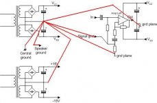
Jens, the rectifiers are shown with a common going straight to central ground. I think it would be better if the rectifier common went to smoothing cap common. It would keep the heavy charging pulse currents in a tight loop that may radiate less EMF/EMI and certainly keep more pulsing out of the central ground.
Jondoe, the mains safety earth is omitted from your connection strategy.
Andrew,
 Maybe i should stop playing with electricity
You're absolutely right. That speaks volumes about my safety measures, doesn't it ?Jondoe, the mains safety earth is omitted from your connection strategy.
Maybe i should stop playing with electricity 
pinkmouse said:The speaker ground should go straight to the star earth.
Hi,
I don't think so.
Here is a better grounding scheme, IMHO:
Regards,
Milan
Attachments

Attachments
i dont see any ground LOOPs anymore, can we get back to sob now ?
btw: i have a thing against Friday 20's, can we set the deadline to Thursday 19 ?
btw: i have a thing against Friday 20's, can we set the deadline to Thursday 19 ?
Of course, you realize that wasn't a mistake at all. I was just humoring a bunch of nitpickers that you are. 😀
Milan
Milan
Hi all,
Moamps,
your grounding scheme shows the central gound coinciding with the PSU commom NO NO NO!!!
You must put a distinct connection from PSU common to central ground to ensure the currents circulating across the smoothing caps do not contaminate the central ground.
A short single wire ( or long wire if your layout demands it) from each PSU common (for stereo or more) is OK, or to be more subtle a copper (brass ) bolt through the PSU common and then put ALL ground connections on the other side of a central nut. So the order of components is bolt head- PSU common - nut - mains earth (optional) - nut - central ground - nut.
This way the large pulse currents from rectifier to caps never pass along the bolt or wire to ground. Only the DC current your amp is returning pass back from central ground to PSU common.
The mains safety earth is COMPULSORY but some may want to use a resistor to connect chassis to central ground and others may decide this resistor is zero ohms. For the zero ohms case the mains earth can tie straight to the grounding bolt.
ground
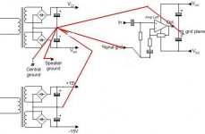
IMHO it is also better to split the commonwire from the rectifiers to the caps.
So each rectifier has his own groundwire.
And the darkgreenwire in jondoes picture must not be there, that is R4 on the pcb.
Loek
IMHO it is also better to split the commonwire from the rectifiers to the caps.
So each rectifier has his own groundwire.
And the darkgreenwire in jondoes picture must not be there, that is R4 on the pcb.
Loek
Oh, i get it.it is also better to split the commonwire from the rectifiers to the caps

You mean something like splitting the hair in 4 ?
Oh, sorry, couldn't help it, i meant 2.

I thought so too.And the darkgreenwire in jondoes picture must not be there, that is R4 on the pcb.
I put it there just to play cat and mouse. See if anybody catches it.
(since it was present in one of Jens's, Post #287).
Attachments
- Status
- Not open for further replies.
- Home
- Amplifiers
- Solid State
- Smaller Leach Amp V1