This is the mid and the cd on the horn taken with a ~4ms window at 1m on axis
Does it look as expected?

Does it look as expected?
A little difficult to say - your 4ms window is going to have odd effects at the low end of the midrange (4ms means you can tell basically nothing below 250Hz, and only vaguely below about 500Hz). You may need to measure closer if your reflections are coming in too soon, and/or use a 'frequency dependent window' to get a somewhat useful though still approximate idea.
Also, without being on a baffle things will behave differently -- the horn is too small to do anything much at below 700Hz, so baffle effects will still be evident, in particular "baffle step". Here's what my drivers looked like, on the baffle, probably closer (and evidently with smoothing, maybe 1/3 octave.... didn't record what it was exactly). These are at different angles, highest ones will be on-axis.

That said, I think you're in the ballpark (the bump near the upper end of the midrange was a bit of a challenge for the crossover design).
Also, without being on a baffle things will behave differently -- the horn is too small to do anything much at below 700Hz, so baffle effects will still be evident, in particular "baffle step". Here's what my drivers looked like, on the baffle, probably closer (and evidently with smoothing, maybe 1/3 octave.... didn't record what it was exactly). These are at different angles, highest ones will be on-axis.
That said, I think you're in the ballpark (the bump near the upper end of the midrange was a bit of a challenge for the crossover design).
Last edited:
thanks
yeah I played with different windows and the peaks remained so I thought I'd put that graph up there as I suspect it will take me the best part of a month (in elapsed time) to the box together
yeah I played with different windows and the peaks remained so I thought I'd put that graph up there as I suspect it will take me the best part of a month (in elapsed time) to the box together
If the peak remains (much beyond what's in my graph), you might consider taking out some of the filler if you can -- more front volume will reduce the top end. Maybe against intuition, narrowing up the channel from cone to port holes can do similar. I wouldn't do that until you've got these on a baffle, though (cardboard can be good for a mock-up baffle)
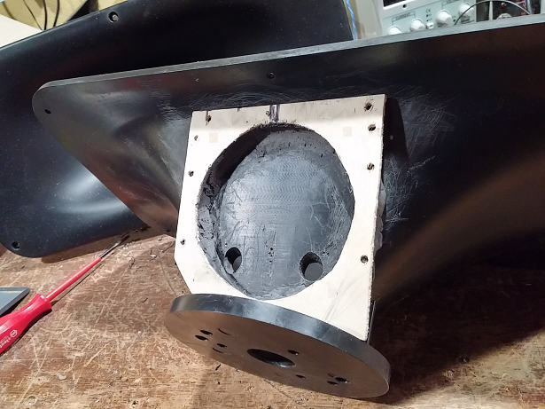
Here is how the midrange mounts to the waveguide. The flat mounting plate board is glued on, and sealed with, epoxy putty. I'll have cutting diagrams and dimensions, as well as hole drilling info in some later posts.
Hi Art,
Would you reveal which epoxy putty you are using and does it do both: glue and seal?
J-b Weld 2 oz. Epoxy Putty with Temp. Range of Up to 300 Degrees F, Gray Model: 8267-S
JBWeld Epoxy Stick, or I've used other brands including Harbor Freight 's cheaper version. Attaches and seals
JBWeld Epoxy Stick, or I've used other brands including Harbor Freight 's cheaper version. Attaches and seals
I made good progress on my first one this weekend. Your instructions are really clear, precise and well thought out, thanks for writing them up.


One question re the woofer mounting, you drill through the baffle and screw from the front. Is it completely impractical to just screw into the rear and not drill all the way through? It feels like it should be doable (to not go all the way through) though that might be because I haven't got the baffle and sides on yet.
FWIW (re the instructions) the one bit that wasn't crystal clear was the woofer cutouts though I think is largely a function of having to translate to metric and use different size bits. The reason being the the outline of the cutout is not marked on the diagram though obviously you can calculate this from the specified drill bit diameter.
Is it completely impractical to just screw into the rear and not drill all the way through?
Well, you could do that before gluing the baffle onto the box, but if you ever needed to remove or replace the woofer you'd be in trouble..... It's already pretty tight in there even to just get your hands in for putting the nuts onto the screws. I don't see it being possible to get a screwdriver in to drive screws from the back.
For the woofer cutout, I guess you mean the oval output port shape? It's not at all critical, just make sure it isn't wide enough to break the seal between inside of box and outside, and leaves enough wood above it for the waveguide to mount. It's a path for air pressure to pass through, vertically centered close to the waveguide edge - not really a 'tuned' area.
I was thinking of attempting to use a butterfly wing screw so I could tighten them by hand alone or perhaps something like Flexible Drill Bit Screwdriver Connectors 300mm Flexible Shaft Soft Shaft Bit Extension Screwdriver Universal Holder Connecting Link Bits Plastic Black Metal Flexible Hex Shank Extension Flex Electric Drill Extention Bit Holder Connect Rod: Amazon.co.uk: DIY & ToolsWell, you could do that before gluing the baffle onto the box, but if you ever needed to remove or replace the woofer you'd be in trouble..... It's already pretty tight in there even to just get your hands in for putting the nuts onto the screws. I don't see it being possible to get a screwdriver in to drive screws from the back.
decided to drill through as per instructions so hopefully get the drivers mounted this weekend and some measurements collected

I got the drivers wired up, took on axis measurements and fed them into your xo design. Leaving aside the droop at the top end (and the fact I haven't taken off axis measurements yet), I'm not sure if it's a bit bumpier than the design, what do you think?


The one at 100Hz is expected -- an interraction between driver/box/and inductors. Couldn't bring that down without clobbering efficiency. But then it's down where room interractions are at play so just another bump into the mix down there.
The one at 2kHz seems pretty high (and in a touchy place). Is your L2 inductor a particularly low-ESR part? You can try bumping R4 an ohm or so to bring it down.
Edit -- oop. Wrong version design. Try adding some resistance in series with L2 to bring down the bump.
The one at 2kHz seems pretty high (and in a touchy place). Is your L2 inductor a particularly low-ESR part? You can try bumping R4 an ohm or so to bring it down.
Edit -- oop. Wrong version design. Try adding some resistance in series with L2 to bring down the bump.
Last edited:
But all told, not terrible. How does it sound?
Maybe Trim R6 (increase) a bit to raise midrange -- there is a diagram in the instruction PDF showing what some of the trim values can do.
Maybe Trim R6 (increase) a bit to raise midrange -- there is a diagram in the instruction PDF showing what some of the trim values can do.
Attachments

Last edited:
It's just in a sim atm so I don't have it to listen to yet unfortunately. I had seen the suggested variations so wanted to get it into a sim first so I could play around with that & also verify the result before I order the parts..
I intend to be crossing this to a (sub)woofer anyway so the peak at the bottom of the woofer is not a problem. The peak at 2kHz with the dip just beneath it was the bit that made me pause to wonder whether this is as per design or not.
what does C7/R3 do btw? IIRC removing it didn't seem to have much of an impact (on a sim with the on axis data only in that is).
c7/r3 are just shaping, they drop the bottom end of the cd down a little in level relative to upper end. Subtle effect
Got that backwards (having a bit of difficulty looking at things today) -- they drop the HF a little, sloping the overall response downwardc7/r3 are just shaping, they drop the bottom end of the cd down a little in level relative to upper end. Subtle effect
I took the speaker outside today and measured to 90 degree horizontally and 60 degree vertically because I wanted to play with the crossover. One thing I noticed on the mid made me wonder where it comes from and whether it requires some tweak to the mid ports.
Here's the normalised horizontal, seems pretty similar to yours except for that notch around 1kHz

not noticeable on the unnormalised view though

and with just the mid active, you can see the peak at ~1080Hz collapses to a dip by ~40 degrees

I can't think where that could come from if not the way I've moulded the ports.
Here's the normalised horizontal, seems pretty similar to yours except for that notch around 1kHz
not noticeable on the unnormalised view though
and with just the mid active, you can see the peak at ~1080Hz collapses to a dip by ~40 degrees
I can't think where that could come from if not the way I've moulded the ports.
- Home
- Loudspeakers
- Multi-Way
- Small Syns