Use the polarized version, but be sure to connect the positive terminal to the grid.
The output cap IS needed, but the value depends on the load. If it's around 10k, use at least 10uF,
with the positive terminal to the collector.
When testing the circuit, measure the collector-ground voltage. It should be close to half the supply voltage.
The voltage at the collector is 16.5V. Instead of 12K I had to make do with 12K4 (2 resistors in series) and 2K2 instead of 2K.
I'm not sure how to technically determine the output load - it's going into a line input of a small mixer.
The result was pretty good, a little noticeable distortion when my phone (MP3 player) was at full volume but the gain level is just about right, touching 0dB on the mixer's VU meter with the gain around 3/4 up - this is about the same level as when I connect my phone directly to the mixer playing the same track at full volume (although there is no distortion).
What is the function of the input and output caps, and how does raising and lowering their values affect the amplifier's performance?
Last edited:
What is the function of the input and output caps, and how does raising and lowering their values
affect the amplifier's performance?
There is DC voltage at both the base and the collector, so a series DC blocking capacitor is necessary at both locations,
to avoid possible problems with devices connected to the input or output. The capacitor passes the signal, but not the DC.
The capacitance value is set by the lowest frequency signal that the circuit is intended to amplify.
If a capacitor is too small in value (uF), the bass would be audibly rolled off. Often the value is selected
so that the bass roll off point is somewhere from 20Hz to 2Hz.
Last edited:
Andrew, thanks for the reply. I'll have to mull that over for a bit, as to be honest it went a little over my head. If it was 20 years ago and I was still fresh out of my City & Guilds 224 electronics course, it might make more sense to mePost1 shows 68k base to emitter.
That value effectively sets the rail voltage that the amplifier will work at.
eg. Assume 1mA passes through the 220r emitter resistor. That gives a voltage drop of 220mVre.
Add on 600mVbe
That gives 820mV across the 68k.
and that leads to 5.66Volts across the 470k
The supply voltage equals 5.66+0.82V = 6.48Vdc when 1mA flows through the emitter resistor.
There is a small error in this simplified calculation. It ignores the base current, but you can compensate for that if you know the hFE of the transistor.
now repeat the calculation for a 5mA emitter current.
That will give a higher rail voltage. You could even try a 10mA emitter current, but that may make the transistor a bit too hot.
You can start with 27Vdc as your supply and work down to the emitter current.
Starting at that end will give a very high emitter current and almost certainly lead to overheating of the transistor.
Do that calculation and see what the predicted dissipation is.

Thanks for the info Rayma, so much to learn! Do the cap values used to achieve that vary depending on the circuit design? (I assume you can't just use the same values for any audio amplifier).There is DC voltage at both the base and the collector, so a series DC blocking capacitor is necessary at both locations,
to avoid possible problems with devices connected to the input or output. The capacitor passes the signal, but not the DC.
The capacitance value is set by the lowest frequency signal that the circuit is intended to amplify.
If a capacitor is too small in value (uF), the bass would be audibly rolled off. Often the value is selected
so that the bass roll off point is somewhere from 20Hz to 2Hz.
Thanks for the info Rayma, so much to learn! Do the cap values used to achieve that vary depending on the circuit design?
(I assume you can't just use the same values for any audio amplifier).
Yes, it's actually the product of the capacitance and the resistance following it, that determines the bass roll-off frequency.
Is it a bad thing that the collector voltage is more than 60% the supply voltage? And is there a way of minimizing distortion further? I slight reduction in gain would be acceptable if it's a trade-off.
If you have done a C&G electronics course, then you have done >>ten times any electronics education I have ever undertaken. And probably >>1000times the average of our Membership.City & Guilds 224 electronics course
C&G sounds very "Londonish"?
If you have done a C&G electronics course, then you have done >>ten times any electronics education I have ever undertaken. And probably >>1000times the average of our Membership.
C&G sounds very "Londonish"?
It was a fairly basic introduction to electronics, but I do wish I could remember everything I was taught (I haven't had much to do with electronics since then until now). We definitely covered some grass roots amplifier theory which would be handy right now!
It was a dated course which had not changed since the 60s (not necessarily bad thing), and I believe they pulled the course completely a year or two after I took it, which is a real shame. It only cost £18.
I am indeed from London, only been in the states about four years 🙂
Last edited:
Is it a bad thing that the collector voltage is more than 60% the supply voltage? And is there a way of minimizing distortion further? I slight reduction in gain would be acceptable if it's a trade-off.
I can redesign this for lower output impedamce, that should help.
Are you willing to replace some of the resistors again?
I can redesign this for lower output impedamce, that should help.
Are you willing to replace some of the resistors again?
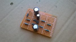
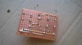
Sure, I just have it tacked together like a skeleton at the moment.
Thank you!
Sure, I just have it tacked together like a skeleton at the moment.
Ok, here are new values for a 27V supply:
Rcollector = 1.3k
Remitter = 300
Base resistor to supply = 24k
Base resistor to ground = 3.6k
Input capacitor=100uF/50V (or more) with the positive lead to base
Output capacitor = 10uF/50V with the positive lead to collector
Decouple the circuit from the supply with 220 Ohms and 470uF/50V (or more)
If this does not give enough gain, bypass the emitter resistor with 470uF/50V (or more)
Thanks rayma, I don't have any 470uF so I'll order some in. Will report back.
Anything from 100uF to 1000uF at 50V will work ok, if you have it.
I used a 220uF on the supply and no bypass cap on the emitter. It works great for the small amount of testing I've given it so far, seems to be just the right amount of gain. Voltage at the collector measures 13.9.Anything from 100uF to 1000uF at 50V will work ok, if you have it.
Thank you for your help 🙂
Attachments
It works great for the small amount of testing I've given it so far
Ok, good luck. We learn this in the first EE course, but don't really use this type of circuit much in practice.
Last edited:
Hi Sreten,
Thanks for the advice! I'd also be happy to try that out if you happen to know of a very compact design.
I have built the preamp below:
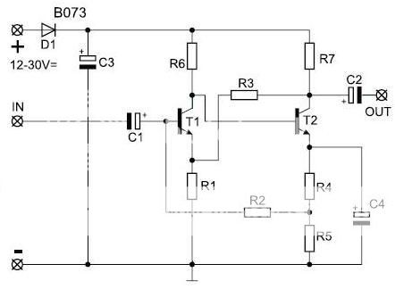
R1 = 560 Ohm
R2 = 160K Ohm
R3 = 47K Ohm
R4 = 560 Ohm
R5 = 560 Ohm
R6 = 68K Ohm
R7 = 2.7K Ohm
C1 = 1uF
C2 = 1uF
C3 = 220uF
C4 = 47uF
...but for some reason when I use it in this system the reverb signal sounds awful through it (noisy) but the dry music signal sounds fine, so I wanted to try something else out.
This schematic looks just like classic two-stage 12AU7 pre amp.
- Status
- Not open for further replies.
- Home
- Amplifiers
- Solid State
- Small basic preamplifier - how to determine the operating voltage?