I'm trying to find out the working voltage range of this preamp. The system I'd like to use it in is running on 27V.
That circuit is designed for a higher supply voltage, so the resistor values will be different for your supply of 27V.
You can guess the design Vcc by assuming that the collector voltage is about half the supply voltage.
I just noticed in the description that it operates best on 9-12V (according to the poster of the circuit)
I would be using a MPSA06 NPN as that's what I have here
http://www.onsemi.com/pub/Collateral/MPSA05-D.PDF
I wouldn't know where to begin if the circuit had to be redesigned for my system. My knowledge is such that I have no idea why 9-12V would be optimal for that circuit. Still learning!
I would be using a MPSA06 NPN as that's what I have here
http://www.onsemi.com/pub/Collateral/MPSA05-D.PDF
I wouldn't know where to begin if the circuit had to be redesigned for my system. My knowledge is such that I have no idea why 9-12V would be optimal for that circuit. Still learning!
I have no idea why 9-12V would be optimal for that circuit.
Many discrete circuits are sensitive to the supply voltages for their best operation.
Last edited:
Is there a way I can optimize the circuit I posted for the higher voltage?Many discrete circuits are sensitive to the supply voltages for their best operation.
Is there a way I can optimize the circuit I posted for the higher voltage?
Ok, how much supply current is available? Also, what input signal level, gain, and maximum output voltage?
What is the minimum input impedance?
Last edited:
The supply current available is 6A. The same supply is also powering a small spring reverb drive and recovery circuit (hence the 27V).Ok, how much supply current is available? What input signal and gain is it for?
As for the gain, I'm not exactly sure but the signal will be the mixed reverb and dry signal from the (spring reverb recovery + direct dry signal after mixing). As the mixing circuit has attenuated the output somewhat it's coming out a little low and just needs a boost (i.e. when feeding the output into a mixer, the gain of that channel needs to be all the way up and the level is OK). Sorry I can't explain that more technically!
As for the gain, I'm not exactly sure
Ok, maybe a gain of ten times, which is 20dB?
Hi,
It is still a very poor solution compared to the decades old
two transistor solutions that are available with research.
rgds, sreten.
It is still a very poor solution compared to the decades old
two transistor solutions that are available with research.
rgds, sreten.
The supply current available is 6A. The same supply is also powering a small spring reverb drive
and recovery circuit (hence the 27V).
Ok, try this for a 27V supply:
Rcollector=12k, Remitter=2k
Base resistor to supply=100k
Base resistor to ground=10k
Input capacitor=10uF/50VNP
Decouple the circuit from the supply with 1k and 100uF/50V
If this does not give enough gain, bypass the emitter resistor with 100uF.
Last edited:
Ok, try this for a 27V supply:
Rcollector=12k, Remitter=2k
Base resistor to supply=100k
Base resistor to ground=10k
Input capacitor=10uF/50VNP
Decouple the circuit from the supply with 1k and 100uF/50V
If this does not give enough gain, bypass the emitter resistor with 100uF.
Thanks very much Rayma, I'll knock that together tomorrow after work tomorrow and try it out.
Hi,
It is still a very poor solution compared to the decades old
two transistor solutions that are available with research.
rgds, sreten.
Hi Sreten,
Thanks for the advice! I'd also be happy to try that out if you happen to know of a very compact design.
I have built the preamp below:
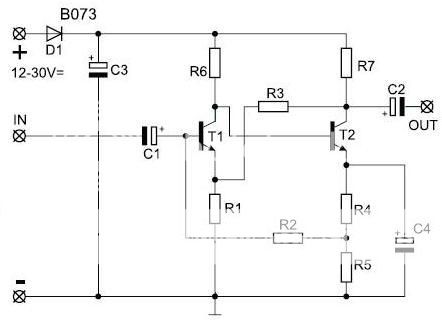
R1 = 560 Ohm
R2 = 160K Ohm
R3 = 47K Ohm
R4 = 560 Ohm
R5 = 560 Ohm
R6 = 68K Ohm
R7 = 2.7K Ohm
C1 = 1uF
C2 = 1uF
C3 = 220uF
C4 = 47uF
...but for some reason when I use it in this system the reverb signal sounds awful through it (noisy) but the dry music signal sounds fine, so I wanted to try something else out.
This is the reverb drive/recovery system I used:
I ended up using quite high values for R14 and R15 to get the desired mix control, but the output needs a boost.
An externally hosted image should be here but it was not working when we last tested it.
I ended up using quite high values for R14 and R15 to get the desired mix control, but the output needs a boost.
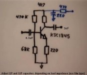
Post1 shows 68k base to emitter.
That value effectively sets the rail voltage that the amplifier will work at.
eg. Assume 1mA passes through the 220r emitter resistor. That gives a voltage drop of 220mVre.
Add on 600mVbe
That gives 820mV across the 68k.
and that leads to 5.66Volts across the 470k
The supply voltage equals 5.66+0.82V = 6.48Vdc when 1mA flows through the emitter resistor.
There is a small error in this simplified calculation. It ignores the base current, but you can compensate for that if you know the hFE of the transistor.
now repeat the calculation for a 5mA emitter current.
That will give a higher rail voltage. You could even try a 10mA emitter current, but that may make the transistor a bit too hot.
You can start with 27Vdc as your supply and work down to the emitter current.
Starting at that end will give a very high emitter current and almost certainly lead to overheating of the transistor.
Do that calculation and see what the predicted dissipation is.
Last edited:
Thanks very much Rayma, I'll knock that together tomorrow after work tomorrow and try it out.
If this does not work well enough, the current output drive capability can be increased. Let me know.
If this does not work well enough, the current output drive capability can be increased. Let me know.
Just a couple of questions. Must the input cap be non polar? I have 10uf caps but they are polarized electrolytics. Also, no mention of the output cap. Not needed in this instance?
Just a couple of questions. Must the input cap be non polar? I have 10uf caps but they are polarized electrolytics.
Also, no mention of the output cap. Not needed in this instance?
Use the polarized version, but be sure to connect the positive terminal to the grid.
The output cap IS needed, but the value depends on the load. If it's around 10k, use at least 10uF,
with the positive terminal to the collector.
When testing the circuit, measure the collector-ground voltage. It should be close to half the supply voltage.
Last edited:
- Status
- Not open for further replies.
- Home
- Amplifiers
- Solid State
- Small basic preamplifier - how to determine the operating voltage?