It does not drift when I blow on it and touching any transistor does not make a real difference.
Reducing R12 from 5k1 to 3k did reduce VAS current variations as now I can read between 10 and 9mA
Offset did not change as it wanders between 3 and -1mV
Reducing R12 from 5k1 to 3k did reduce VAS current variations as now I can read between 10 and 9mA
Offset did not change as it wanders between 3 and -1mV
Thank you Kean .... It is a good result for a 1st tryIt does not drift when I blow on it and touching any transistor does not make a real difference.
Reducing R12 from 5k1 to 3k did reduce VAS current variations as now I can read between 10 and 9mA
Offset did not change as it wanders between 3 and -1mV
I tried 57v, 50v, 30v and the behaviour is similar. My bench psu is regulated...Does supply voltage change the VAS current?
I tried r12 1k5 and variations are much slower and the difference is only 10ma to 9.5ma. Will try higher ips current and 1k2 for r12
After trying Cordell's solution (4k7ohm between collectors of the IPS mirrors) and having verified that it also sets the VAS current with fluctuations, I decided to go back to my solution.
Reduced R12 to 1k and placed small heatsinks over the VAS buffers Q4 and Q6.
It is reasonably stable (it changes every second) but within 11.6m_A and 11.3mA.
I lost some dB in LF Loop gain and THD20 went up a bit but damping factor at 100Hz is 5k7 so bass is not compromised.
Now I will prepare the boards for installation in the P130 modular amp and proceed with listening tests.
Now, with the IPS placed in the real amplifier with a linear PSU, offset can be fine tuned to within 1 and -1mV
VAS current is much more stable.
VAS current is much more stable.
[...]
The "proper" solution is a common mode control loop which regulates the VAS current (which is common mode) without affecting the forward gain (which is differential mode).
[...]

Cheers, E.
Common mode versus diff mode.... would you care to explain the difference?
Cheers, E.
Hi Ricardo,
We distinguish two kind of currents in case of a complementary VAS stage: the sum of the two collector (or emitter) currents (i.e. common mode) and the difference of them (i.e. differential mode). The latter, being the signal, is supplied to the next stage.
Regarding your current solution, please also have a look at this post about tradeoffs between open loop gain and amount of feedback (by mens of Rfb) to define/stabilize the common mode current.
Cheers, E.
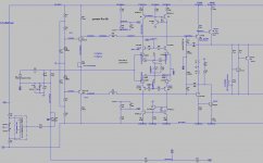
Your solution is quite complex....
With 4mA in each input jfet I am having trouble to set VAS current lower than 16mA
I managed to have the same vdrop over the mirror resistor R2 and the VAS emitter resistor R11.... but....
With 4mA in each input jfet I am having trouble to set VAS current lower than 16mA
I managed to have the same vdrop over the mirror resistor R2 and the VAS emitter resistor R11.... but....
Attachments
Increasing VAS Re to 47ohm gets me in the ballpark.
One thing your circuit provides is very good stability even with TMC... With local feedback set to 10k there is ne phase dip below UG... very good.
Did you build your circuit Edmond ?
Does the current limiting Q11 Q16 stiffen the VAS DC common mode current ?
One thing your circuit provides is very good stability even with TMC... With local feedback set to 10k there is ne phase dip below UG... very good.
Did you build your circuit Edmond ?
Does the current limiting Q11 Q16 stiffen the VAS DC common mode current ?
Nice to hear.Increasing VAS Re to 47ohm gets me in the ballpark.
One thing your circuit provides is very good stability even with TMC... With local feedback set to 10k there is ne phase dip below UG... very good.
No. I don't like building amps that much. I'm a designer in the first place.Did you build your circuit Edmond ?
Under normal conditions current limiting should be completely off.Does the current limiting Q11 Q16 stiffen the VAS DC common mode current ?
Cheers, E.
I was thinking that it was the presence of Q11 Q16 that fixed current in the VAS..... If it is only a security measure (current limiting) we could do without it.Nice to hear.
No. I don't like building amps that much. I'm a designer in the first place.
Under normal conditions current limiting should be completely off.
Cheers, E.
Happy New Year.....
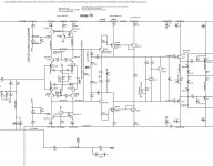
Please look at my latest design.
It does not need local feedback.
VAS current is set by a mirror based CCS so it is independent of IPS current.
OLG is maximized so THD is minimized.
The only doubt relates to the connection of the VAS buffer... it is almost like a darlington but not quite.
Hope you have the time to look at it and let me know if it can be done 🙂
Attachments
You still need a resistor in colector of the current mirror like Bob Cordell solution. I use 33K ohm in my simulation.Happy New Year.....
Please look at my latest design.
It does not need local feedback.
VAS current is set by a mirror based CCS so it is independent of IPS current.
OLG is maximized so THD is minimized.
The only doubt relates to the connection of the VAS buffer... it is almost like a darlington but not quite.
Hope you have the time to look at it and let me know if it can be done 🙂
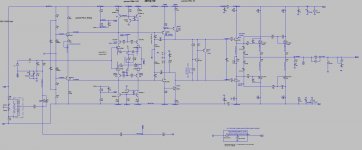
My most recent development...
Here I do not use resistors to try to set a fixed current in the VAS... instead I implemented a ccs that sets a fixed voltage in the bases of the VAS "helper" transistors.
It seems to provide a very stable VAS current without compromising OLG.
I am not sure if this solution is works in reality so I hope you guys can help me with your comments.
I did not have the time to include my models in the asc files so I am including those in a txt file.
Attachments
-
 RCP130 EVO8.75 LOOPGAIN.JPG174.5 KB · Views: 122
 -
 RCP130 EVO8.JPG130 KB · Views: 125
 -
RCP130 FCS EVO8.754.pdf145 KB · Views: 98
-
RCP130 BIEL FCS GLENK EVO8.754 NEW FLOATING LED CCS TIAN PROBE.asc28.2 KB · Views: 72
-
RCP130 BIEL FCS GLENK EVO8.754 NEW FLOATING LED CCS TRANSIENT.asc27.5 KB · Views: 75
-
RCAUDIO MODELS 2021.txt375 KB · Views: 79
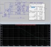
I modified the circuit values to have a stiffer CCS setting VAS current and added two 150k resistors R12 and R57 so to increase it's impedance and maximize Loop Gain.
Simulations seem very good but there is surely room for optimization.
Maybe the ccs current setting resistor should be split in two with center tap grounded ... ??
I really need your input here.
Simulations seem very good but there is surely room for optimization.
Maybe the ccs current setting resistor should be split in two with center tap grounded ... ??
I really need your input here.
Attachments
See my message.
Use driver current common mode. They behave almost or as colse as i can think to the Vas current.
For your vas and driver it may bee a idea haviind a diode in they're common emitter's.
This for youre mirror transistor is getting a terrible low colektor emitter voltage. Here models fail !
Use driver current common mode. They behave almost or as colse as i can think to the Vas current.
For your vas and driver it may bee a idea haviind a diode in they're common emitter's.
This for youre mirror transistor is getting a terrible low colektor emitter voltage. Here models fail !
- Home
- Amplifiers
- Solid State
- Slone amp final solution ?