😎
I forgot to mention - R9-11 might be bigger (1W) - this is actually
a true CFA . 😀
OS
I wondered about those when I was populating the board so I checked the schematic. You are usually pretty good about noting that. How critical are the values of those three resistors. I don't have either of those values in 1W. I can order them of course, but if there is a range I may be able to get it going now.
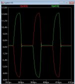
On the Krypton-V, I haven't pulled the Super pair yet because I want to see if I can get it to work with them. The AX-14 IPS I made has them and it works great. I did try the anti-parallel diodes that BV suggested. It doesn't like the ones on Q3-6. Latches badly at clipping. The ones on Q1/2 are fine but I'm not sure they help either. I tried it through the new lateral OPS that Valery designed. It does show a little latching at clipping but that is at 47vac into an 8R load. I'll get some pictures of how the latching looks.
Blessings, Terry,
Blessings, Terry,
As you recommented
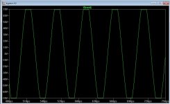
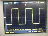
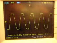
Perfect ( tame square wave response) , now to get it to clip nice. 🙂
You now have a(properly working) enhanced classic sansui input stage.
If we deal with the saturation/"sticking" , a quality amp of this flavor
we will have (yoda speak) 😀 .
PS - BV ... i'll try all those tricks. I'll even tap the Glen Klienschmidt / E
Stuart (ancient) threads for hints.
OS
Terry , R9-10-11 .....
Just make sure you have the proportions right.
For example , R9/10= 68R -82R-100R - would be R11= 1.8K- 2.2k- 2.7k.
Eyesee is current FB , but the IC's current is small. Less current is tolerable.
THD might rise slightly with 100R/2.7k - but stability is constant.
OS
Just make sure you have the proportions right.
For example , R9/10= 68R -82R-100R - would be R11= 1.8K- 2.2k- 2.7k.
Eyesee is current FB , but the IC's current is small. Less current is tolerable.
THD might rise slightly with 100R/2.7k - but stability is constant.
OS
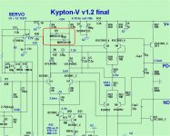
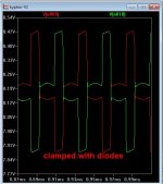
Thimios , try as you are - and just add the 2 anti-parallell diodes at input.
(below - circled).
edit - I hope it looks like this (below 2)
OS
(below - circled).
edit - I hope it looks like this (below 2)
OS
Attachments
Last edited:
Here you are.Thimios , try as you are - and just add the 2 anti-parallell diodes at input.
(below - circled).
edit - I hope it looks like this (below 2)
OS
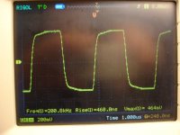
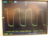
First and secon.picture with C6=12pf
All other with C6=5p6
Attachments
-
 DSC08220.JPG540 KB · Views: 127
 -
 DSC08219.JPG612.8 KB · Views: 112
 -
 DSC08218.JPG582.9 KB · Views: 120
 -
 DSC08217.JPG597.9 KB · Views: 138
 -
 DSC08216.JPG530.8 KB · Views: 127
 -
 DSC08215.JPG607.9 KB · Views: 137
 -
 DSC08214.JPG567.6 KB · Views: 413
 -
 DSC08212.JPG551.8 KB · Views: 429
 -
 DSC08211.JPG561.3 KB · Views: 457
Last edited:
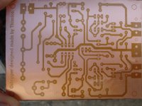
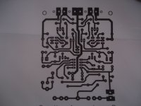
Hi all, has anybody build the diamond h amplifier from post#5249?
I think OS is still putting the finishing touches of that design. No board layout yet.
OS,
The two diodes you just had Thimios add to his input section, are these to stop current sharing or robbing from one side of the input from the other? I am just trying to understand how you use those reversed polarity diodes between a circuit like that. Thanks for the education.
The two diodes you just had Thimios add to his input section, are these to stop current sharing or robbing from one side of the input from the other? I am just trying to understand how you use those reversed polarity diodes between a circuit like that. Thanks for the education.
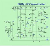
The "Infidel" - lose your faith in the CFA.
That's an understatement.
I will use BCxxx for the diamonds , and run these "jewels" at 12V.
This adds 12db PSRR but we still have a very low device count.
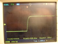
I thought the concept simulation was good - I had no idea !! (below 1)
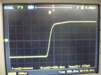
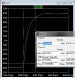
613V/us and I am not even approaching over-shoot (low phase margin).
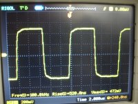
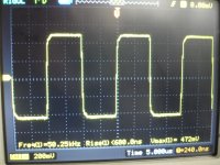
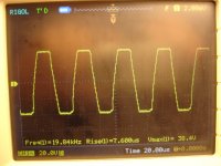
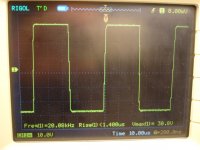
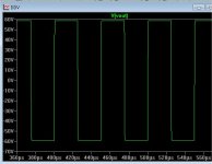
Rail to rail squarewaves (below 2) - it "eats them" for breakfast. 😀
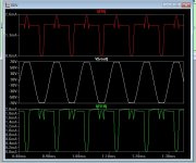
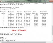
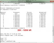
20K is <10ppm (below 3) 20hz is also perfect (below 4).
Then the overload response - self clamping !! 🙂 (below 5)
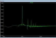
FFT is glorious - cancellation of even and odd (as predicted - 6)
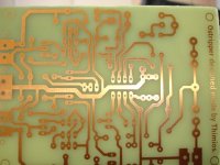
Final schema to PCB(below 7) - tonight ! Beats most in some things , beats
them all with all factors considered.
If my amp was done - I would print this out NOW !
OS
I think OS is still putting the finishing touches of that design. No board layout yet.
That's an understatement.
I will use BCxxx for the diamonds , and run these "jewels" at 12V.
This adds 12db PSRR but we still have a very low device count.
I thought the concept simulation was good - I had no idea !! (below 1)
613V/us and I am not even approaching over-shoot (low phase margin).
Rail to rail squarewaves (below 2) - it "eats them" for breakfast. 😀
20K is <10ppm (below 3) 20hz is also perfect (below 4).
Then the overload response - self clamping !! 🙂 (below 5)
FFT is glorious - cancellation of even and odd (as predicted - 6)
Final schema to PCB(below 7) - tonight ! Beats most in some things , beats
them all with all factors considered.
If my amp was done - I would print this out NOW !
OS
Attachments
Here you are.
First and secon.picture with C6=12pf
All other with C6=5p6
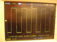
A tiny bit of "sticking" , but a stable amp with a second stage that
sees a lot less current.
I will "re-issue" the "V" with these changes. A good amp ! 🙂
PS - the "bow" at the top/bottom is gone ... NO saturation at all.
OS
Please OS you must work on this IPS (kypton-v),from a little listening test it is singing like CFA in high frequencies ,crystal clear with strong bass.😱A tiny bit of "sticking" , but a stable amp with a second stage that
sees a lot less current.
I will "re-issue" the "V" with these changes. A good amp ! 🙂
PS - the "bow" at the top/bottom is gone ... NO saturation at all.
OS
OS,
The two diodes you just had Thimios add to his input section, are these to stop current sharing or robbing from one side of the input from the other? I am just trying to understand how you use those reversed polarity diodes between a circuit like that. Thanks for the education.
What happens (below) is that this input stage is SO sensitive to the
clipped feedback ... the first stage tries real hard to supply the second stage
with enough voltage to "satisfy" the saturation (below).
Instead of trying to clamp the saturation at the voltage stage , why
not stop it right at the source ? with the diodes (below 2).
It seems to work. 🙂 Kypton -V was hard to tame ... but a very
common classic design that needed to be explored.
OS
Attachments
Last edited:
Please OS you must work on this IPS (kypton-v),from a little listening test it is singing like CFA in high frequencies ,crystal clear with strong bass.😱
Bimo said the same thing - that's why I "kept on it". 🙂
PS - you now have a enhanced "classic Sansui" - these designs have a "cult following" in the audio world.
OS
Last edited:
 Thanks OS for all you have done. I know you will put forth the same ANAL UNMUNTZING effort on the HEC Output that I am hoping you will consider FET for the outputs TOO.
😎
I forgot to mention - R9-11 might be bigger (1W) - this is actually
a true CFA . 😀
OS
What about R5 & R6?. What rating should those be? Should the values chage with rail voltage?
Thanks, Terry
Eyesee
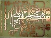
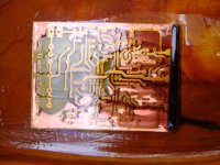
From the beginning
From the beginning
Attachments
-
 DSC08242.JPG617.7 KB · Views: 158
 -
 DSC08239.JPG613.8 KB · Views: 168
 -
 DSC08238.JPG578.4 KB · Views: 172
 -
 DSC08233.JPG578.5 KB · Views: 161
 -
 DSC08230.JPG551.5 KB · Views: 182
 -
 DSC08229.JPG608.9 KB · Views: 185
 -
 DSC08228.JPG524.8 KB · Views: 195
 -
 DSC08224.JPG539.2 KB · Views: 224
 -
 DSC08245.JPG558.3 KB · Views: 168
 -
 DSC08246.JPG556.8 KB · Views: 185
Last edited:
- Home
- Amplifiers
- Solid State
- Slewmaster - CFA vs. VFA "Rumble"