I'm not Borys, but they appear to be screen shots from a Rigol 1000Z series scope ...
That screen looks every bit as nice as the pricey Agilent scope I used at work!
I use DS1054Z 50 MHz Digital Oscilloscope | Rigol - Beyond Measure
Its 4channel so nice for digital stuffs to 🙂
Some say it's software hackable to get all the extra features 🙂
MSO1054Z 50 MHz
MSO1074Z 70 MHz
MSO1104Z 100 MHz
Regards
Its 4channel so nice for digital stuffs to 🙂
Some say it's software hackable to get all the extra features 🙂
MSO1054Z 50 MHz
MSO1074Z 70 MHz
MSO1104Z 100 MHz
Regards
Yes I have DS1054 scope but I bought the version without signal generator 🙁.
Scope is good for the money but not perfect, have quite lot of noise, I thik it is not only the DAC problem but PSU in the scope. Generally it is OK for a DIYer.
I got the packet with the mosfets, so I will solder rest of the OPS tomorrow.
Scope is good for the money but not perfect, have quite lot of noise, I thik it is not only the DAC problem but PSU in the scope. Generally it is OK for a DIYer.
I got the packet with the mosfets, so I will solder rest of the OPS tomorrow.
... Scope is good for the money but not perfect, have quite lot of noise, I thik it is not only the DAC problem but PSU in the scope. Generally it is OK for a DIYer...
Hmm ...
Well I guess that is why the Agilent that I used cost $6K plus dollars
Is the FFT feature of the TEK TDS754a worthwhile for doing DIY power amp live circuit analysis?
Tektronix TDS 754A 500MHz 2GSA s Oscilloscope w 13 1F 2F Rackmount 60 Day Warr | eBay
Tektronix TDS 754A 500MHz 2GSA s Oscilloscope w 13 1F 2F Rackmount 60 Day Warr | eBay
A small observation from today.
Few posts above I have posted pictures with simple mosfet OPS with only one pair of popular IRFP transistors soldered (82R gate stoppers), all was working really nice and stable.
Today I have soldered 3 pairs of irf540/9540 mosfets to the same OPS, it started to show some parasitic oscillation so I had to increase gate stoppers from 82R up to 330R (at 150R the oscillations were still present).
Now I am just wondering if It was caused by the two more pairs of OP transistors or just by the type of the transistor.
I will try to check it tomorrow.
It is not so simple as it looks like.
Regards
Attachments
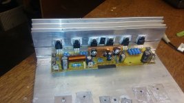
Beware, base stoppers had to be set as close from the chips as possible: I was shocked by your wires as I am with the long transistor's legs in your photo. Remember we are dealing there with something around 10MHz.A small observation from today.
Few posts above I have posted pictures with simple mosfet OPS with only one pair of popular IRFP transistors soldered (82R gate stoppers), all was working really nice and stable.
Today I have soldered 3 pairs of irf540/9540 mosfets to the same OPS, it started to show some parasitic oscillation so I had to increase gate stoppers from 82R up to 330R (at 150R the oscillations were still present).
Now I am just wondering if It was caused by the two more pairs of OP transistors or just by the type of the transistor.
I will try to check it tomorrow.
It is not so simple as it looks like.
Regards
Last edited:
Esperado
But the version with the wires was performing really good. My problems have started afted I have soldered 3 pairs of irf transistors. Maybe the irfp transistors are less sensitive to parasitic oscillations.
I have placed the gate stoppers just by the transistor leg, the track on the pcb is no longer than 1-2mm.
I am wondering how to match correctly the gate resistors, just by the hardware measurements and tests on the bench ?
On the mosfet amplifiers they have values from 47R up to 470 or even 1k !
The most used is approx 220R.
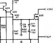
Indeed. Remember that any wire (track/leg) length is a coil and the gate parasitic capacitance are high on those IRF.The most used is approx 220R.
cordell has recommended series R-C from gate to ground instead with a smaller value gate resistor.
see attached excerpt.
might be worth a try ...
mlloyd1
see attached excerpt.
might be worth a try ...
mlloyd1
Attachments
Last edited:
I don't know. In a way, it linearize a little the gate capacitance, in an other it increase the load of the VAS/driver at HF ...cordell has recommended series R-C from gate to ground instead with a smaller value gate resistor.
see attached excerpt.
might be worth a try ...
Hi guys
Kryten C is super.
Incredible sound quality, better than NAD-H 1.2.
I can use the site Q1,2 JFET 2SJ74 / 2SK170 ????
Thanks
Kryten C is super.
Incredible sound quality, better than NAD-H 1.2.
I can use the site Q1,2 JFET 2SJ74 / 2SK170 ????
Thanks
cfa-vfa prototypes
Nad look at post# 832,963,967.988,989,1005
Spooky #1247,1267,1292,1301
Gnome v1.3 #1455,1467,1485,1500,1516,1531,1538,1567
Symasui #1642,1671,1672,1673
Cfa ver.1.2 #1754,1756,1757,1784
Cfa v1.3 #2976
Wolverine ver1-c #3543,3564,3637,2279
Kypton C #4797,4765
Kypton V #5261,5282
Eyessee #5521
Kypton ND #6830,6850,6888
Infidel an unsuccessful IPS #5385
Ostriper schematic list look at post # 1
I hope this is a complete list and may be useful.
Last edited:
Thimios thank you. I had proposed to OS to build a website for him about this work, but it seems he does not care.
Christophe,
I'm not so sure he wasn't interested in your proposal. The fact that we haven't seen anything from him for awhile is a bit troubling but I suspect he has had some family issues come up. I don't think anyone has heard from him? I just don't want him to disappear as NuwaveGuy did on the 02headphone thread. Let's give him some time and space before we start trying to chase him down.
I'm not so sure he wasn't interested in your proposal. The fact that we haven't seen anything from him for awhile is a bit troubling but I suspect he has had some family issues come up. I don't think anyone has heard from him? I just don't want him to disappear as NuwaveGuy did on the 02headphone thread. Let's give him some time and space before we start trying to chase him down.
I hope this is a complete list and may be useful.
The "SYMETRI" simple complimentary (Bimo) has many supporters. ROBUST topology.
"Symetri-Cascode" post #8349. You can run the .asc file to confirm ~ 25% lower THD with your models.
The "spookyamp" (leach amp) also uses complementary cascoded inputs, with a Hawksford VAS instead of the second complementary diff VAS used in Symetri. The BC5xxC transistors have a 4db noise figure. Cascoding the Symetri inputs also allows using ultra low (2db)noise JFETS as input transistors.
- Home
- Amplifiers
- Solid State
- Slewmaster - CFA vs. VFA "Rumble"