Especially careful, considering he is one of the best friends of Mr Murphy.Yeah, I also decided not to argue with Mr Harry Nyquist 😉
Thanks Valery,
I will try that this morning. Hopefully that will make this pair usable. I think I will build a pair with MJL4381/4302 and see how those work out. I asked about those before building this pair and was told the MJL21193/94 might be better at the higher voltage because of their higher current capabilities. I will try your cap suggestions and report back. The Sankens would probably work but on these boards you would have to drop down to three pair in order for them to fit.
Blessings, Terry
Last edited:
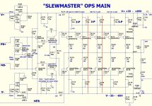
Ok, let's go back to OPS stability with different output devices for a minute.
I did some simulations, actually confirming what's been said above.
Analyzed circuit is my tube-hybrid IPS together with SlewMonster OPS.
OPS creates additional pole on overall frequency response curve.
Picture 1 - with faster NJW3281/1302 transistors this pole is around 4.6 MHz and 5.5 db below the unity gain level. Acceptable - we cross unity gain with 20 db/decade slope.
Picture 2 - with slower MJL21193/21194 the pole is located at 3.2 MHz and actually lays on the edge - roughly at the unity gain. This is a problem - frequency response slope changes from 20 db/decade to 40 db/decade here and we don't want 40 db/decade to be located at the unity gain level.
Picture 3 - this is how we can solve it - increase the value of C107, C109 (pre-drivers shunts) from 33pF to, let say, 150pF. The pole stays at 3.2 MHz, but moves down to -6 db - and we are fine again.
Anyway, the faster devices are the better. SC2922/SA1216 Sankens would be a good choice here as well, with Ft = 50 MHz and Cob = 250 pF (half of any of the above).
Hope this helps.
Cheers,
Valery
This begs the question then, in a triple EF, do we benefit at all from different device choices for driver and pre-driver, especially to tailor response to the very capable MJL2119X devices? What is optimal with respect to their Ft? Given the choice I'd suggest more compatible drivers and pre-drivers, though slugging them with a capacitor does work. I always figured relative speeds should be:
Pre-Driver - Fastest of the three
Driver - Fast, somewhere between the pre-driver and output speed
Output - Slowest of the three
But perhaps there is a better combination, or we simply want slower drivers and pre-drivers when we are choosing to use slower outputs. Some comments were made some time ago in this thread about it but I'm not sure I can find them now.
Thanks Valery,
I will try that this morning. Hopefully that will make this pair usable. I think I will build a pair with MJL4381/4302 and see how those work out. I asked about those before building this pair and was told the MJL21193/94 might be better at the higher voltage because of their higher current capabilities. I will try your cap suggestions and report back. The Sankens would probably work but on these boards you would have to drop down to three pair in order for them to fit.
Blessings, Terry
You can get Sankens in a to-3P package (IIRC Sanken calls it the MT-100).
I was primarily looking at the SOA when I suggested the MJL2119x devices. I honestly didn't think the speed of the device would become an issue. To be fair, my prototype build did use the faster type of outputs.
For those who want a 3P option the MT-200 Sankens would be really nice...
...
Thimios fried some slow 21195/6 OP's. The slewmaster design likes
faster OP's (30mhz +) ... obviously !
...
OS
Wish I had remembered this comment earlier.
In fact, I also considered MJL21193/21194 as no problem at a first glance, without even looking at its Ft, and I have them in my SlewMonster prototype (3 pairs as this is the number I could buy quickly) and it does not oscillate in my case. I only started looking deeper after the point was raised here.
But the pole is there, in my case it's just a little bit lower (on vertical axis).
So let's call this a "potential " issue so far.
I did an interesting simulation earlier with regards to a commercial design with CFP topology and enormously heavy compensation - it used rather slow TIP35/36 output transistors and behaved very unstable even with all the 680pF shunt caps in place. Simply changing those to big Sankens allowed running it stable even with no caps at all - same nature, with faster Sankens the pole moves far to the right and down on the graph and this is what we basically want from it...
Last edited:
Where we can find a supplier for these MAG....
Mouser haven't them on stock and i read somewhere that Farnell stock some fake 😱
Mouser haven't them on stock and i read somewhere that Farnell stock some fake 😱
Last edited:
Where we can find a supplier for these?
Mouser haven't them on stock and i read somewhere that Farnell stock some fake 😱
Don't know if they are fake : Power-Complementary
Thanks Idefixes ,no one know🙂Don't know if they are fake : Power-Complementary
I have two pairs 2sc3264,a1295 from the past,i'm sure these are original ,tosted many times at 400Khz and hi volume .
Last edited:
...I have two pairs 2sc3264,a1295 from the past...
Another excellent pair from Sanken in MT-200 big boxes
Profusion is reliable supplier, for SANKEN too.Don't know if they are fake : Power-Complementary.
Profusion is reliable supplier, for SANKEN too.
Farnell should be too, and as profusion they can be abused from supplier...
Marc
Hi Guys,
I am building a pair of the SlewBaby OPS boards. They are like the Slewmaster OPS except they have only 2 pair outputs and the drivers are TO-220 devices.
My question is should the current be different through the TO-220 devices than the TO-247 devices? Should I use a higher value for R113?
I'm planning to use 2SC3423-Y/A1360-Y for the predrivers and cap mutiplier, BD139 for the VBE multiliers, MJE15032/33 for the drivers and MJL4281/4302 for the outputs. It will most likely be run with +-56v rails. Does anyone see any problems with my device choices? Do you see any other components that need to be changed in the attached schematic?
Thanks, Terry
Attachments
Hi Terry, I don't see any problems. No stability issues expected.
Power dissipation of TO-220 drivers will not exceed 1.6W in normal operation (with R113 = 68R quiescent current = 20mA, Pd = 1.12W). It may raise up to 5.5W in case you run a square wave at full power, but a) it is still acceptable assuming a decent heatsink b) it's a very rude way of using an audio amplifier 😉 Anyway, the output devices will already feel much more stressed at that time.
Cheers,
Valery
... CFAs are in particular sensitive to (stray) capacitances... this CFA specific sensitivity...
Seems to me that VFAs equally have a pole due to stray capacitance at the -ve input. The lower impedance of this input in a "CFA" should push this pole further out.
So for audio power amps, that are all limited to similar speed by the OPS, this should actually favour the CFA (a little!).
Very different for ICs, as you note, where the speeds of typical "CFA"s make this pole an issue for them, probably more often than for typically slower VFA.
Best wishes
David
Makes sense to me
Never made serious studies about this, but, at first glance, i would try to make each stage faster than the previous,Pre-Driver - Fastest of the three
Driver - Fast, somewhere between the pre-driver and output speed
Output - Slowest of the three
to avoid TIM.
At the second look, if the amp is class AB, we would like to have the 'comparator' faster than the output stage to cure crossing distortion ?
- Home
- Amplifiers
- Solid State
- Slewmaster - CFA vs. VFA "Rumble"