5th,
I think that would be the CFA-XH BV3
Hmm I've built BV2, I thought that was the most up to date version and the attachments list doesn't list any BV3 apart from thimios' measurement.
From what I recall we've got the CFA, CFA-XH, CFA-XH BV1, CFA-XH BV2, and the CFA-XH OS stripper mod from BVs ideas.
BV mentioned one more modification that has become the BV3. I would have to go back through the posts to find that change.
Okay OS made v1.1/1.2/1.3. BV then really modded v1.3 twice. The first mod was fairly simple that included the first stage of the IPS into the feedback loop. The second mod added more components, altered the compensation scheme and included the output stage within the feedback loop. The third mod was identical to the second but included an additional way to trim the DC offset and added VAS protection. Neither of these changes were really significant over version two and shouldn't affect the sound in any way. They just make the amp easier to set up and more robust.
What thimios is calling version 3 is what BV called version 2.
At some point, on the new PCB, when it's done, I could measure the performance with the VAS protection disabled and see if it changes anything. It shouldn't, but if it does then that would be one reason why it could actually sound worse. Or thimios has his BV mod 2, from post 2974, set-up incorrectly (it should perform identically to the previous version).
I have three working versions of the CFA -HX. The one that matches the boards we had made, The one BV called mod 1 and the one that he called mod BV. I installed the 50k pot and two 27K resistors between D5 and D6. That works well for adjusting the offset. I know I have already said this but they sound the same however they don't look the same on the scope. The one called mod 1 has the squarest looking 100k waves but it has a little over shoot at 20k. That may be because I still have it set with too high a gain, I'm not sure. I may try lowering the gain and see if that clears that up. The latest mod has more rounded 100K square waves than the others. BV said that may be because he changed C2 to 680p. The other versions had 150p there. I keep meaning to swap that out and see. If I were going to vote on a new board it wound be mod 1. It works very well and has the fewest parts. I'm sure BV added the addition parts for a reason, and the pot between the diodes does make adjusting the offset easier.
Maybe with a new layout you might see more benefits.
Blessings, Terry
Maybe with a new layout you might see more benefits.
Blessings, Terry
I have this CFA MODIF.3 at the bottom of my list because i have listen all INP playing the same music track again and again. .In this track there is a bell playing
It is crystal audible with some INP and not with others.This modif.CFA isn't clear (crystal) playing this bell.
Simple CFA-X is one of crystal playing.
What is the best for high frequency at listening test?
1)SIMPLE CFA Post#710
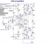
2)CFA MOD. 3(BV)
3)schematic of modif.vers
4)simple cfa
2)CFA MOD. 3(BV)
3)schematic of modif.vers
4)simple cfa
Attachments
Last edited:
This is a difficult question.What is the best for high frequency at listening test?
I don't know the winner.
cfa-x ,Nad,Gnome,Symasui,Spooky ,i can say All are in the same good listening
Thimios, are you using MJE340/350 as predriver or VAS? Try to avoid use them in signal path. And "crystal" highs may be sign of unstability, CFA with TMC compensation (end stage in local NFB loop at HF ) is very fast and prone to this, and critical to output stage PCB topology and wiring (parasitic L and C in local NFB loop ). You can try to make it "slower", e.g. disconnect R25, R26 (change TMC to normal compensation), or increase value of CM1, CM2 to 100pF and C17,18 to 220p. And input filter (R1,C2) should be the same for comparison, same also voltage gain.
Last edited:
The whole mess in this thread, one say I could not hear any difference, one says this one is like this, others like that, one is looking to measurements only, one is calculating the sound ... I wonder what would be a consensus at the end?
As many people as many opinions. Whom to believe? Who's right?
I'd say KISS 😀
As many people as many opinions. Whom to believe? Who's right?
I'd say KISS 😀
Truth is that one can only build and decide for one self. The mirrored CFA-x only needs good housekeeping to be good. And I would also prefer to have it running on higher currents to avoid switching in the feedback pair at high voltage swings
No i didn't use mje340-350,i used ksa1381E- ksc3503EThimios, are you using MJE340/350 as predriver or VAS? Try to avoid use them in signal path. And "crystal" highs may be sign of unstability, CFA with TMC compensation (end stage in local NFB loop at HF ) is very fast and prone to this, and critical to output stage PCB topology and wiring (parasitic L and C in local NFB loop ). You can try to make it "slower", e.g. disconnect R25, R26 (change TMC to normal compensation), or increase value of CM1, CM2 to 100pF and C17,18 to 220p. And input filter (R1,C2) should be the same for comparison, same also voltage gain.
VAS current is same 4.5mA BOTH versions.
The whole mess in this thread, one say I could not hear any difference, one says this one is like this, others like that, one is looking to measurements only, one is calculating the sound ... I wonder what would be a consensus at the end?
As many people as many opinions. Whom to believe? Who's right?
I'd say KISS 😀
Once the sound is as clean as our ears can detect, how do you improve it? If want to change it from there, change speakers. I can only speak for myself. I am trying these different mods because I want to learn, not because I think the sound will improve. Surely this is no longer a "Very Simple Symmetrical Amplifier".
I didn't see that mod .2 before. I must have glossed over it. I will have to look at my latest version and see how close it is. I may try out BV's latest suggestions. I will also look to see if I used mje340/350. I know I did in the OPS for the predrivers.
Hi Guys,
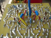
I got bored so I went ahead and populated one of my Spooky boards. Man, I forgot how tough it is populating a board without silkscreen. I must have flipped that board over 200 times during the build. Anyway I got it all populated ready to test. I didn't have 100R pots so I put 200R's in there and then just dialed them down to 100R each. I installed 475R resistors between the PD/ND outs the the NFB and brought it up slowly. I was measuring the offset and drop across the outputs, looking for about 4.5V. Well the total output measured about right but I had 2V offset. I checked each output to ground and I have like .8V at PD+ and -3V at ND-. No matter what I tried, I could not dial out the offset. I double and triple checked everything but couldn't find an error. So this morning I populated the other board being especially careful with each part. I change to KSA992/KSC3503 for the vas due to BV's suggestions to see if that would have an affect. I hooked up the new board and brought it up and it looked good. I was able to set the VAS current to 4.5mA and zero offset. I'm thinking I have solved the mystery and then I notice that I didn't plug in the TL072. The socket was empty. So I drean down the PSU and then install a new TL072 and bring it back up. Same problem as before. -3.1V on ND- and .850V on PD+ I tried adjusting it out but cannot. One of the things that attracted me to this IPS was that it had a servo, and I had never used ne before. I guess I need some pointers for setting one up.
Thanks, Terry
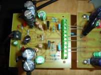
Hi Terry ,my Spooky is on the post#1267.Hi Guys,
I got bored so I went ahead and populated one of my Spooky boards. Man, I forgot how tough it is populating a board without silkscreen. I must have flipped that board over 200 times during the build. Anyway I got it all populated ready to test. I didn't have 100R pots so I put 200R's in there and then just dialed them down to 100R each. I installed 475R resistors between the PD/ND outs the the NFB and brought it up slowly. I was measuring the offset and drop across the outputs, looking for about 4.5V. Well the total output measured about right but I had 2V offset. I checked each output to ground and I have like .8V at PD+ and -3V at ND-. No matter what I tried, I could not dial out the offset. I double and triple checked everything but couldn't find an error. So this morning I populated the other board being especially careful with each part. I change to KSA992/KSC3503 for the vas due to BV's suggestions to see if that would have an affect. I hooked up the new board and brought it up and it looked good. I was able to set the VAS current to 4.5mA and zero offset. I'm thinking I have solved the mystery and then I notice that I didn't plug in the TL072. The socket was empty. So I drean down the PSU and then install a new TL072 and bring it back up. Same problem as before. -3.1V on ND- and .850V on PD+ I tried adjusting it out but cannot. One of the things that attracted me to this IPS was that it had a servo, and I had never used ne before. I guess I need some pointers for setting one up.
Thanks, Terry
Some posts later are about some issue ,please have a look,this may be help
Complement to KSC3503 seems KSA1381, guess it's a typo 😉...........I change to KSA992/KSC3503 for the vas due to BV's suggestions to see if that would have an affect..........
Hi Terry ,my Spooky is on the post#1267.
Some posts later are about some issue ,please have a look,this may be help
Hi Thimios,
I'm reading though that now. You used much lower rails than me so it is a little difficult to compare some of the readings. OS dealt with your low rails so that is not helping as much as I had hoped. He also is using different part numbers than what is on the schematic you used and that is adding confusion. I did some more testing this morning. With the opamp unplugged and offset at 0 I get this;
V+=72.2
V-=-72.2
PD+=1.7V
ND-=1.7V
VR8=1.605
VR9=1.770
VR12=3.134
VR13=3.125
VR10+R11=1.175
VD7=3.103
When I plug in the TL072
PD+=1.5
ND-=2.1
I don't have anything in the LC spot because it says optional.
Trying to adjust the offset away with the pots doesn't work. I think the servo keeps trying to fight it.
Suggestions?
Hi BYRTT
Yes Typo
KSA1381/KSC3503
Blessings, Terry
I don't know if it's important but could it perhaps be that the servo wont work correctly if the output stage isn't actually in place?
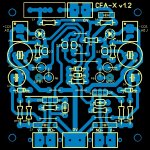
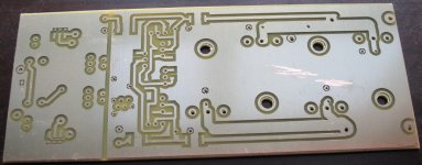
Version two of my CFA PCB.
I decided to go with a more ground plane orientated design this time. I figured I might as well give it a go. Not that there's a lot of stuff really flowing through the ground return in this design, but it's easy enough to try.
Version two of my CFA PCB.
I decided to go with a more ground plane orientated design this time. I figured I might as well give it a go. Not that there's a lot of stuff really flowing through the ground return in this design, but it's easy enough to try.
Attachments

- Home
- Amplifiers
- Solid State
- Slewmaster - CFA vs. VFA "Rumble"