Some pictures to CFA-X mod1 simulation and schematic
Attachments
Last edited:
Lateral mosfets are easy to drive, and can be driven direct from the VAS, if it has more than 5mA current
To drive 1nF capacity to 100V p-p at 10kHz is about 6mA p-p needed. And what about fast transients and higher capacity?Lateral mosfets are easy to drive, and can be driven direct from the VAS..
Some pictures to CFA-X mod1 simulation and schematic
Hi BV,
Can you post the asc file? I can read the values you are using. It looks like you added more compensation. I think I can modify my boards to do what you have there and would like to try it.
Thanks, Terry
To drive 1nF capacity to 100V p-p at 10kHz is about 6mA p-p needed. And what about fast transients and higher capacity?
What does this have to do with the Slewmaster? 😕
Terry,
If I have been following that discussion correctly that statement that BV just made would be directed at the LC designed VSSA type of amplifier.
If I have been following that discussion correctly that statement that BV just made would be directed at the LC designed VSSA type of amplifier.
Discussion of lateral MOSFETs is out of context in this thread IMHO, but it would relate more closely to the VSSA than the SlewMaster project.
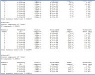
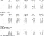
Someone asked earlier how the sim looks at 1K rather than 10K so I ran the latest BV model at both 10k and 1k. Hopefully I did this right. I'm attaching screen shots from the error log. First the 10K and then the 1K. I'll attach the asc file and Slewmaster.txt in case someone wants to check my figures.
BV, I changed some to the part numbers so they make sense to me on my PCB. Hope you don't mind.
Blessings, Terry
BV, I changed some to the part numbers so they make sense to me on my PCB. Hope you don't mind.
Blessings, Terry
Attachments
Some pictures to CFA-X mod1 simulation and schematic
Your a genius , BV. That is VFA typical PSRR ... on a CFA. 😱
ps - all that by just including the first stage in the miller loop !
OS
It would be nice when someone proposes a change such as BV has just done that they highlight the changes in red when they do this so you don't have to compare schematics to find the change. Or at least circle the drawing please.
So this will require a mod to the circuit drawings or how hard to modify the V1.3 version for the what sounds like significant improvement in psrr over the earlier version. Sounds like the superiority of the VFA design is going to be found moot at some point if the CFA's keep being improved with these minor systematic changes.
So this will require a mod to the circuit drawings or how hard to modify the V1.3 version for the what sounds like significant improvement in psrr over the earlier version. Sounds like the superiority of the VFA design is going to be found moot at some point if the CFA's keep being improved with these minor systematic changes.
Last edited:
Probably best if Jason can just do a new layout but since I have extra IPS boards I am just going to modify them. I will post my intentions for review before I actually do the cutting.
Blessings, Terry
Blessings, Terry
I don't think there is any real issue with the exisiting CFA-XH v1.3, it looks like BV is just showing us there are alternatives. I would certainly do a new layout (v1.4?), if warranted. This very rapid iterative process makes my increasingly shy of having more boards made, I don't want to end up sitting on a pile of perfectly useable PCBs just because someone 'tweaks' a schematic and everyone decides they want that. I will have to wait and see what shakes out.
Member
Joined 2009
Paid Member
Sounds like the superiority of the VFA design is going to be found moot at some point if the CFA's keep being improved
I don't think it makes sense to view either as superior. There are so many factors that make a good amplifier-speaker system.
For example, the singleton input is a CFA, but it's single-ended harmonic profile has much to do with the resulting sound as does the low impedance feedback loop.
It's difficult to compare 'sound' between CFA and VFA when there are many factors that differ between the relevant topologies. I remember feeling the same about memory distortion - the topologies proposed for eliminating memory distortion provide for much greater OLG and linearity so you can't evaluate the impact of memory distortion independently. If I weren't so lazy I'd try a comparison with my TGM7 which keeps much of the topology and parts in common between the CFA and VFA versions, all on the same pcb - but as I don't expect to find enough differences between the two topologies I haven't been motivated to try it yet.
There are always tradeoffs, just have to pick your favourites.
Last edited:
I explained the finer points of the LED metrics in the last post.
"OPT's" 1-2 ...
1 = ground reference of the input cascode. (just an option).
2= use of a active clamp for VAS saturation (instead of DC6).
Both methods result in the same clipping behavior.
(below example - R31 + Q14)
D. Self mentions and shows example of "opt 2"...
Edit - like the badger ... reverse leakage of DC6 is important. Find one with nA to pA
reverse leakage rating. The "option 2" (transistor) ... most have very low leakage --
OS
Sorry OS that I didn't respond back,
I really don't want to be too complicated on the layout so I just going to ask you simple questions, man I know you are rolling with new IPS wow! I don't want to bother you too much 😀
ok I'm making a pretty look of Wolverine V1.2 "for myself of course lol" I know there is version 1.3 and I can do that later, but example to be simple if I put it it together all parts all good to go then I can just use the "OPT1" ("I think is a jumper that goes there I'm not sure to be honest") then DSC=MMSD4148 is use and OPT2 is not in use ? I like more the DSC option to use 🙂
I really want it to make sure what I'm thinking is correct 🙂
sorry for any grammar errors
Juan
Attachments
Last edited:
No real issue.
The CFA-Xh is "present" SOTA for a VSSA/CFA.
BUT ! BV has indeed brought a "deal breaker" to the table. LC ... eat your
heart out !! 😀
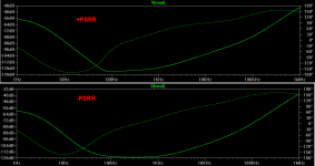
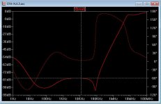
(below 1) the LF PSRR is 20+ DB better. -90db 20-200hz , only
going to -80 at 10hz and 20K.
BV changed the OPS filtering to the predriver only ... 470u + 68R. (he cheated).
On the present OPS , this can be done by increasing the value of the
1W resistors or increasing the driver/pre decoupling value.
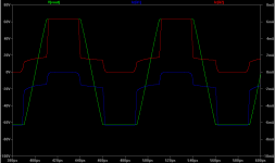
Realistically (below 2) the main improvement (not to ignore the psrr 🙂 )
is the THD , some distortion common mode cancellation is definitely
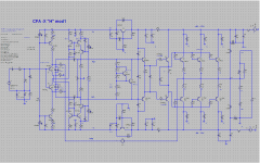
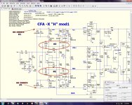
happening. #2 on the schema (below 3) shows the compensation and
the blockers feeding a common 68R to ground.
#1 shows the lack of zener's ( ditch the zeners 😀 😎 ) , as well.
PS - those are the changes , Kindhorn.
So , we have 20db better PSRR and <15ppm THD @ 20K 120V levels.
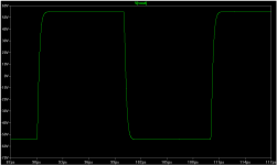
All the other metrics ... slew / loop gain , stay at thier previously
impressive levels !! 😎
EDIT - All these factors would indeed be hard to achieve even with
the "better" spooky . 😱😱
EDIT 2 - I simmed with the 5-pair OPS + keentoken's modified models.
I previously simmed with BV's "cheat" for -110db PSRR - PSSR plot below is realistic
for the 5- pair present OPS.
OS
The CFA-Xh is "present" SOTA for a VSSA/CFA.
BUT ! BV has indeed brought a "deal breaker" to the table. LC ... eat your
heart out !! 😀
(below 1) the LF PSRR is 20+ DB better. -90db 20-200hz , only
going to -80 at 10hz and 20K.
BV changed the OPS filtering to the predriver only ... 470u + 68R. (he cheated).
On the present OPS , this can be done by increasing the value of the
1W resistors or increasing the driver/pre decoupling value.
Realistically (below 2) the main improvement (not to ignore the psrr 🙂 )
is the THD , some distortion common mode cancellation is definitely
happening. #2 on the schema (below 3) shows the compensation and
the blockers feeding a common 68R to ground.
#1 shows the lack of zener's ( ditch the zeners 😀 😎 ) , as well.
PS - those are the changes , Kindhorn.
So , we have 20db better PSRR and <15ppm THD @ 20K 120V levels.
All the other metrics ... slew / loop gain , stay at thier previously
impressive levels !! 😎
EDIT - All these factors would indeed be hard to achieve even with
the "better" spooky . 😱😱
EDIT 2 - I simmed with the 5-pair OPS + keentoken's modified models.
I previously simmed with BV's "cheat" for -110db PSRR - PSSR plot below is realistic
for the 5- pair present OPS.
OS
Attachments

Last edited:
What happens when you sim it at 20kHz, 120V P-P into 4 Ohms? This is where I run most all my simulations at some point.
Bela
That IS ... 20K THD 120v p-p (above 2)
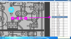
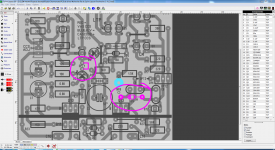
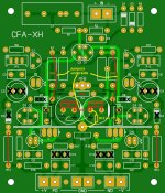
Have a look at these mods to the current CFA-XH boards. Some value changes aren't shown but the cuts and jumpers are.
Let me know if you see something I missed.
I'm not advocating that we follow this direction but since I have extra boards I want to try it. DIYA baby!
Let me know if you see something I missed.
I'm not advocating that we follow this direction but since I have extra boards I want to try it. DIYA baby!
Attachments
Last edited:
- Home
- Amplifiers
- Solid State
- Slewmaster - CFA vs. VFA "Rumble"