You should just need to centre the pots and adjust one or the other to null the offset. By design the currents should be close to the design target. That worked fine for me anyhow.
Hi Jason,
Center as in 100R each? I'm seeing about 1.2V across the 150R resistors with 1K load resistors on the output. Is this OK?
Thanks, Terry
Hi Jason,
Center as in 100R each? I'm seeing about 1.2V across the 150R resistors with 1K load resistors on the output. Is this OK?
Thanks, Terry
Yes set the pots 'mid-way' to 100Ω. The 150R resistors have current from both the VAS and the Hawksford cascode flowing through them and therefore are not an accurate indicator of VAS current. If you are using a dummy load of two 470R resistors tied across the PD and ND you should read about 4V or so across the pair.
Hi Jason,
I had 1k resistors tied from PD and ND to the NFB. I was seeing a little over 5V across each. That is with the pots set to 200R (max). I will try again this morning with 470R and the pots set to 100R each.
One other question. I couldn't find the LED's listed in the schematic. I installed UV LED's in D9 & D10 and Red jellies in D5 & D6. Are the LED's critical? I can of course get some Reds from radio shack if necessary. All I have in the 3mm are white and UV. The only Reds I have are the small jellies.
Hi Jason,
I had 1k resistors tied from PD and ND to the NFB. I was seeing a little over 5V across each. That is with the pots set to 200R (max). I will try again this morning with 470R and the pots set to 100R each.
One other question. I couldn't find the LED's listed in the schematic. I installed UV LED's in D9 & D10 and Red jellies in D5 & D6. Are the LED's critical? I can of course get some Reds from radio shack if necessary. All I have in the 3mm are white and UV. The only Reds I have are the small jellies.
Some new reds are 1.8-1.9V , My LTspice model is 1.65V(Vf) for the reds.
Older gallium arsenide phosphide (GaAsP) , found in 70's/80's e-waste...
are the perfect 1.65Vf.
Since we have trimmers as standard for the CCS's ... the new ones
will work but may be REAL bright.
Edit - the reds are the most critical ... a 1.8+V red might require a 60+R
increase in the trimmer adjustment.
The blues/UV's just set cascode/hawksford references , most are 3V+ ... not
as critical (green @ 2.6Vf all the way to white @ 3.6Vf will do).
(UV is perfect at @ 2.9-3.0V) , and the light output will not "blow you away".
PS - UV will look cool with UV reactive tubing on the NFB return wire from
the OPS 😀 . And , older red leds will last 50 years or more at my low current
settings ... plus not be "overpowering" like the new chinese ones. 😎
OS
Hello guys
I decide to go with IPS "Wolverine" v1.3 and I have a few questions,
I was making a Part list and checking the data of the diodes and the LED's
are surface mount type
D3 = NSCW100 Blue/UV
D5 = QTLP690C RED VAS CCS
will any UV light LED will work ?
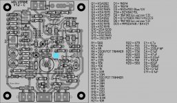
and the other question I see on the layout I see this "OPT2 and OPT2" I do not know what is it ? I'm not sure, look like an option to do something else 🙂
Juan
I decide to go with IPS "Wolverine" v1.3 and I have a few questions,
I was making a Part list and checking the data of the diodes and the LED's
are surface mount type
D3 = NSCW100 Blue/UV
D5 = QTLP690C RED VAS CCS
will any UV light LED will work ?
and the other question I see on the layout I see this "OPT2 and OPT2" I do not know what is it ? I'm not sure, look like an option to do something else 🙂
Juan
Attachments

Hello guys
I decide to go with IPS "Wolverine" v1.3 and I have a few questions,
I was making a Part list and checking the data of the diodes and the LED's
are surface mount type
D3 = NSCW100 Blue/UV
D5 = QTLP690C RED VAS CCS
will any UV light LED will work ?
and the other question I see on the layout I see this "OPT2 and OPT2" I do not know what is it ? I'm not sure, look like an option to do something else 🙂
Juan
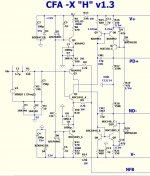
I explained the finer points of the LED metrics in the last post.
"OPT's" 1-2 ...
1 = ground reference of the input cascode. (just an option).
2= use of a active clamp for VAS saturation (instead of DC6).
Both methods result in the same clipping behavior.
(below example - R31 + Q14)
D. Self mentions and shows example of "opt 2"...
Edit - like the badger ... reverse leakage of DC6 is important. Find one with nA to pA
reverse leakage rating. The "option 2" (transistor) ... most have very low leakage --
OS
Attachments
Last edited:
Some new reds are 1.8-1.9V , My LTspice model is 1.65V(Vf) for the reds.
Older gallium arsenide phosphide (GaAsP) , found in 70's/80's e-waste...
are the perfect 1.65Vf.
Since we have trimmers as standard for the CCS's ... the new ones
will work but may be REAL bright.
Edit - the reds are the most critical ... a 1.8+V red might require a 60+R
increase in the trimmer adjustment.
The blues/UV's just set cascode/hawksford references , most are 3V+ ... not
as critical (green @ 2.6Vf all the way to white @ 3.6Vf will do).
(UV is perfect at @ 2.9-3.0V) , and the light output will not "blow you away".
PS - UV will look cool with UV reactive tubing on the NFB return wire from
the OPS 😀 . And , older red leds will last 50 years or more at my low current
settings ... plus not be "overpowering" like the new chinese ones. 😎
OS
Hi OS,
Thanks for the clear explanation. I checked and mine are dropping 1.8 but since they are small jellies they are not too bright so good to go there. I have a question about the adjustment. I used 475R load resistors and with it set to 4.5V across them the output should be about 4.7mA. However, at that setting, R6 drops about .980V so a little over 2mA. Is that OK?
Thanks, Terry
2 ma is good for the input pair. My 1.6ma was set for specific models/voltages.
With the trimmers , if you need 2ma to get 4.5-5+ ma at VAS = AOK 🙂 .
Keep in mind , when you calculate the hawksford current .... you must subtract
the LED current (blue/UV If - @R19) from the main VAS total current (@ R16/21).
PS - you can raise the value of R19 to get the same VAS current with less input
pair current (leds will use less current , requiring less current on R16/21)... another
"tweak".
Last edited:
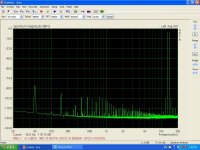
Please look at these.You've got some real issues going on there that need figuring out.
The wiring up of amplifiers, with respect to return currents, both in terms of wiring up the amplifier for every day use and then wiring it up for measurements, is critical.
The results that you've posted clearly show that there is something contaminating the results from how they should otherwise be.
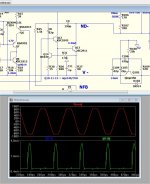
As a simple test could you perform a measurement, like above, 14VRMS out, but without any load connected?
Any help is useful
Attachments
Last edited:
2 ma is good for the input pair. My 1.6ma was set for specific models/voltages.
With the trimmers , if you need 2ma to get 4.5-5+ ma at VAS = AOK 🙂 .
Keep in mind , when you calculate the hawksford current .... you must subtract
the LED current (blue/UV If - @R19) from the main VAS total current (@ R16/21).
PS - you can raise the value of R19 to get the same VAS current with less input
pair current (leds will use less current , requiring less current on R16/21)... another
"tweak".
I hooked it up to th OPS. Everything looked OK until I hooked up both channels to a CD player. As soon as I plugged in both inputs the bias shot up so I shut it down and rechecked both channels. I am seeing oscillation on both now. So I unhooked the IPS on both channels and hooked them up to the scope using the 475R load resistors and they look really, really good with square waves all the way to 150mHz. The OPS worked fine with the little VSSA front end. I am going to hook those back up to check and see if something got hurt somehow.
Terry,
Can't you also hook these input sections up without the output sections connected and do the same test with square waves and look for any oscillation in those section by themselves? Not sure what you would do about a feedback loop, perhaps someone knowledgeable can tell you how to check the input section by itself.
Can't you also hook these input sections up without the output sections connected and do the same test with square waves and look for any oscillation in those section by themselves? Not sure what you would do about a feedback loop, perhaps someone knowledgeable can tell you how to check the input section by itself.
Terry,
Can't you also hook these input sections up without the output sections connected and do the same test with square waves and look for any oscillation in those section by themselves? Not sure what you would do about a feedback loop, perhaps someone knowledgeable can tell you how to check the input section by itself.
That is what I meant when I said "So I unhooked the IPS on both channels and hooked them up to the scope using the 475R load resistors"
I used two 475R resistors, one from PD and one from ND and attached them to the NFB point on the IPS. I hooked the scope to that point and then played Square waves through the IPS. They look beautiful. For some reason it oscillates when hooked up to the OPS sections. I just remembered that I haven't played anything through these OPS since I mounted them on this heatsink. They were mounted on separate heatsinks before. I will try to hook up the small VSSA IPS later today and see if those oscillate as well. If so then it has to do with the new mounting. I have the other pair of OPS as well. They have the Symasym IPS hooked up to them. I was going to leave it that way so I could A/B them bt maybe I should try these CFA-XH boards on those just to see.
So many possibilities. 😀
Wow rediscovering the wheel once again 😉How can one mimic Thermaltrack BJT? 🙄
Well by using SMD BJT as a temp sensor by glueing it to the central pin of a power transistor, to the point where it comes out from a plastic case. There's usually wider area of a copper pin just of the right size to accomodate SMD BJT. Copper pin actually serves as the best temperature transferring media from a die to the outside world.
I would love to be able to tell you more myself.
I built my 'tester' OPS with some 2SA1302 and 2SC3281 I bought quite a number of years ago, before I was even aware of counterfeit semiconductors. It appears that all those 2SC3281 I have are likely fakes since I popped one with just some basic testing 🙁. After cracking it open I could see the itty-bitty die compared to the real McCoy. The markings I can say with what I know now look dubious.
I have to order some devices from Mouser or Digi-Key. I think I will go for some ON Semi MJL2119x output pairs and some NJW0302 / NJW0281 as drivers. Any reason to want a faster output device like the MJL1302A / MJL3281A (or similar from Fairchild - quite a bit cheaper)?
Please look at these.
Any help is useful
What RMS voltage are you measuring at the OP? The problem with sound cards is the absolute level is relative and you need a reference somewhere. I think that hum / buzz would be audible if you placed a speaker across the output (with no signal) . Try disconnecting the mic input gnd connection. This may break the ground loop.
That is what I meant when I said "So I unhooked the IPS on both channels and hooked them up to the scope using the 475R load resistors"
I used two 475R resistors, one from PD and one from ND and attached them to the NFB point on the IPS. I hooked the scope to that point and then played Square waves through the IPS. They look beautiful. For some reason it oscillates when hooked up to the OPS sections. I just remembered that I haven't played anything through these OPS since I mounted them on this heatsink. They were mounted on separate heatsinks before. I will try to hook up the small VSSA IPS later today and see if those oscillate as well. If so then it has to do with the new mounting. I have the other pair of OPS as well. They have the Symasym IPS hooked up to them. I was going to leave it that way so I could A/B them bt maybe I should try these CFA-XH boards on those just to see.
So many possibilities. 😀
I know the problem. Thimios had it. C13-14 !!! Remove and replace those
33pF's into "CM1 and CM2" pads.
OS
This came up before? That's my problem. When things get too technical I find I'm reading the words but there's no pictures being formed. 
I wondered what the CM1 &CM2 were for. Now I know.😀
I'll try it.
Thanks, Terry
I wondered what the CM1 &CM2 were for. Now I know.😀
I'll try it.
Thanks, Terry
Please look at these.
Any help is useful
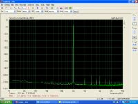
Right. First of all, this helps to confirm what both I and triplej suspected. At least partially.
I do not know if you have read Self, thimios, but there are a few reasons why performance like this can occur.
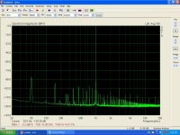
Basically what we're looking at is low distortion with the sound card in loop-back mode and then distortion that looks almost identical with the amplifier working without a load. Things then turn sour when the load is connected. This isn't necessarily a surprise, as measuring power amplifier can be quite a challenge.
As the distortion is low without a load connected we can assume that there is no non linearity being cause by resistors or capacitors within the voltage divider to the PC and the feedback within the amplifier itself.
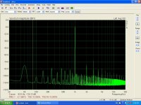
When you connect a load to an amplifier this causes several things to happen all of which occur because current is now having to flow within it.
The first issue is that as current is drawn from the supply rails it causes them to become modulated to the tune of what is imposed on the output. When a class AB amplifier is operating significantly out of class A the positive supply rail ends up being modulated by the positive going half of the signal alone with the reverse happening for the negative. When you decouple the power rails the decoupling capacitors couple some of this into the ground and contaminate it. This is why there are two ground listed in the schematics. The decoupling capacitors create a dirty ground into wherever they are connected and the sensitive areas of the amplifier end up seeing this and it destroys the amplifiers performance.
The way to go about making sure this doesn't happen is to split the grounds up inside the amplifier. Any decoupling capacitor should basically be connected to the same trace on the PCB and then this trace be connected back to the common point back at the reservoir capacitors.
The other areas on the PCB, such as the grounds where the current sources, the feedback network and the input network connect to need to go back to the common point via their own wire, however this in and of itself isn't enough. What you need to do is take a short piece of wire from the common point at the reservoir caps and connect it to a small piece of PCB. You then connect the wire from the feedback ground back to this piece of PCB. This keeps the dirty and clean grounds separate.
The return from the load, ie the negative loudspeaker terminal, needs to connect back to the clean ground and anything else, such as muting circuits needs to go back to the dirty one.
Doing the above sorts out one of the most insidious forms of distortion, the contamination of the clean signal ground from the dirty ground.
The next thing that happens with the modulated signal on the power rails is that it can inductively couple into sensitive areas of the amplifier circuitry too. If you've got power rails coming into the board via flying leads then how they are positioned can be critical. You need to keep them away from the input stage. This distortion gets worse as frequency increases and usually isn't particularly bad at 1kHz. That said, if this distortion is being a problem is can also be due to bad layout and cannot be fixed without a board revision.
If these two things are sorted out then there are a couple of other things that can cause a problem with the amp itself but they are usually quite benign.
The problem when you connect the amplifier to the computer is that you create loops between the mains wiring, the PC, the input connectors of the amplifier, the output of the sound card, the input of the sound card and the output of the amplifier. There is one important thing that you must make sure does not happen with this set up, otherwise it will destroy the measured performance. What can happen is that the return current from the load can end up flowing through the shield of the input connector/cable. If this happens it's bad.
Hopefully some of that might give you some things to try.
This came up before? That's my problem. When things get too technical I find I'm reading the words but there's no pictures being formed.
I wondered what the CM1 & CM2 were for. Now I know.😀
I'll try it.
Thanks, Terry
Here is the update 😱 (below) , DO NOT USE the C13/14 (shunt).
CM1/2 gave perfect operation when thimios switched.
Sorry - I have a lot going on now.
OS
Attachments
Are R17 & R18 then necessary? They are part of the 'VAS abuse' compensation scheme, were they not? I have been testing the IPS in isolation without them (or the shunt Cs) and it seems to work without them.
- Home
- Amplifiers
- Solid State
- Slewmaster - CFA vs. VFA "Rumble"