Just get shipping notice for more 5P OPS and some CFA-XH IPS. When I have them I will either open a new thread in the group buy section or resurrect my earlier OPS group buy thread. Stay tuned!
Looking forward to that Jason. Any chance of making the integrated 2P boards with the input section?
I may have missed this, but OS, when you've been posting the simulated THD results what conditions were they done under with respect to drive level and load?
@ 5th element
This is what I made to get a square wave out of my laptop.R11 can be a 20k pot if you want to get a close 50-50 duty cycle. Rise and fall times are better than my 10 MHz scope can measure. The 5V is from an old cell phone charger.
( schematic, 1k output, 1MHZ output)
Thanks, that looks interesting. I'll probably give it a go 🙂
Just get shipping notice for more 5P OPS and some CFA-XH IPS. When I have them I will either open a new thread in the group buy section or resurrect my earlier OPS group buy thread. Stay tuned!
Let me know please, I am very interested and would like in on a group buy.
Thanks
Looking forward to that Jason. Any chance of making the integrated 2P boards with the input section?
I wasn't really planning on having those made. It was really just a little exercise in 'I wonder what that would look like...'. I didn't think there would be much demand for the 'Baby', since most folks are all about more power. It isn't too tough to generate a set of files and send out for them if enough interest presents itself.
The big caveat with this SlewMaster project is that the number of possible permutations of OPS and IPS are significant. A specific combination may appeal to a select few, so integration limits appeal. I think allowing individual choice negates most issues. I'd rather have additional OPS made with varying numbers of pairs and keep it modular rather than pursue integration in the long run.
Jason,'
Could you supply me with the Gerber files or whatever I would need to make some of the integrated 2p boards? I'll have some made for my application for prototypes. Eventually I want to integrate the active Saleen Key cross-overs with the amplifier section.
Could you supply me with the Gerber files or whatever I would need to make some of the integrated 2p boards? I'll have some made for my application for prototypes. Eventually I want to integrate the active Saleen Key cross-overs with the amplifier section.
I didn't think there would be much demand for the 'Baby', since most folks are all about more power.
Some folks are, some are not. For most it's all about the first watt. Pano's thread a while back confirmed that most people seldom need anything close to 100 watts for their normal listening, most around or below 30 watts.
Most people build single pair low power stuff and there's a good reason for moving up to two pairs even just for low power.
The lovely thing about this thread is that people can experiment with several different state of the art input stages. To me this is the main draw to the thread, not the output power!
Putting things into context though, the EF3 output stage, with 0R22 RE
resistors runs hot. Optimally biased we're talking 107mA per transistor. In the five pair model, run at 80volts, that's 85 watts of idle dissipation, which is significant.
If you run a two pair version on 40 volt rails, we're talking 17 watts idle, which is a lot more comfortable. It also works very well with a number of heat sinks that people probably have lying around.
214mA of standing bias in each half of a two pair version also gives you (if I've calculated it right) about 0.7 watts of class A. This is also nice for the first watt idea as you'll probably get the majority of your every day listening in full class A, at least I know I will. Then you'll transition smoothly into an optimum bias class AB if you need more (which I will do on occasion).
I mean sure, more power is always nice, but it does come at a cost. I can see lots of people being curious about experimenting, but not wanting to spend a lot. Going for a fully populated, full power version, isn't exactly a cheap or small build.
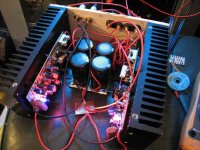
After the first board was a success I've now etched and put together a second board, so now I get stereo 😀
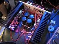
A case in point (no pun intended) about the 2 pair version, is that it fits inside a relatively compact case. The heat sinks here are 10x20x4cm and although the transformer sits in another box, it all fits comfortable in the small form factor.
I still need to build the DC/delay turn on protection board with MOSFET relays, but there's plenty of room at the front of what will be the case for that.
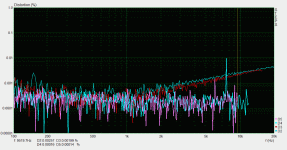
I've changed the RE resistors down to 0R2, and biased them a little hotter than the 107mA per device as would be optimal for 0R22 RE resistors. This should give me a little bit more than the 0.7 watts in class A as calculated before. Running a distortion sweep at 2.83vRMS into my 9.4 ohm load indicates that the amp could quite possibly be in class A for this. In my previous forays into class A going from an optimally biased class AB, to class A doesn't really affect the level of HD2 and HD3, but it does pretty much remove any higher order harmonics from the equation.
Here's the distortion sweep, where you can see the only thing that's really measurable is the HD2 and HD3 above ~1khz. The rest is just sitting comfortably in the noise. (Ignore the two spikes in the HD4 and 5 as they are measurement artefacts.)
The only thing I need to do now is optimise the resistor values in the protection circuitry.
Attachments
Nice work and very nice numbers ----- comment on power output level needed. It is true that to be loud enough and then some, not a lot of 'average' power is needed. But to be 'clean' sounding, often more power is needed just to avoid clipping.... especially exacerbated by larger room size and amount of sound absorption.
Power reserve or headroom is needed to avoid occassional or not so occassional clipping and its distortion generation... you need the power to get the undistorted complete dynamic range on the best recordings. A 20dB average to peak ratio or greater is reasonable.
THx-RNMarsh
Power reserve or headroom is needed to avoid occassional or not so occassional clipping and its distortion generation... you need the power to get the undistorted complete dynamic range on the best recordings. A 20dB average to peak ratio or greater is reasonable.
THx-RNMarsh
Last edited:
Nice work!Hello,
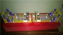
due to the availability of certain transistors I created my own layot for the IPS.
CFA-X with bc-series for to-92 transistors attached to Baby ops.
I´ll try to keep the smoke in on weekend.
J
Good luck.
Thimios.
Nice work ,is this the SMD ver?Some folks are, some are not. For most it's all about the first watt. Pano's thread a while back confirmed that most people seldom need anything close to 100 watts for their normal listening, most around or below 30 watts.
Most people build single pair low power stuff and there's a good reason for moving up to two pairs even just for low power.
The lovely thing about this thread is that people can experiment with several different state of the art input stages. To me this is the main draw to the thread, not the output power!
Putting things into context though, the EF3 output stage, with 0R22 RE
resistors runs hot. Optimally biased we're talking 107mA per transistor. In the five pair model, run at 80volts, that's 85 watts of idle dissipation, which is significant.
If you run a two pair version on 40 volt rails, we're talking 17 watts idle, which is a lot more comfortable. It also works very well with a number of heat sinks that people probably have lying around.
214mA of standing bias in each half of a two pair version also gives you (if I've calculated it right) about 0.7 watts of class A. This is also nice for the first watt idea as you'll probably get the majority of your every day listening in full class A, at least I know I will. Then you'll transition smoothly into an optimum bias class AB if you need more (which I will do on occasion).
I mean sure, more power is always nice, but it does come at a cost. I can see lots of people being curious about experimenting, but not wanting to spend a lot. Going for a fully populated, full power version, isn't exactly a cheap or small build.
After the first board was a success I've now etched and put together a second board, so now I get stereo 😀


A case in point (no pun intended) about the 2 pair version, is that it fits inside a relatively compact case. The heat sinks here are 10x20x4cm and although the transformer sits in another box, it all fits comfortable in the small form factor.
I still need to build the DC/delay turn on protection board with MOSFET relays, but there's plenty of room at the front of what will be the case for that.
I've changed the RE resistors down to 0R2, and biased them a little hotter than the 107mA per device as would be optimal for 0R22 RE resistors. This should give me a little bit more than the 0.7 watts in class A as calculated before. Running a distortion sweep at 2.83vRMS into my 9.4 ohm load indicates that the amp could quite possibly be in class A for this. In my previous forays into class A going from an optimally biased class AB, to class A doesn't really affect the level of HD2 and HD3, but it does pretty much remove any higher order harmonics from the equation.
Here's the distortion sweep, where you can see the only thing that's really measurable is the HD2 and HD3 above ~1khz. The rest is just sitting comfortably in the noise. (Ignore the two spikes in the HD4 and 5 as they are measurement artefacts.)

The only thing I need to do now is optimise the resistor values in the protection circuitry.
Can you tell us which software used for measurements?
Thimios.
2Terry
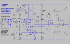
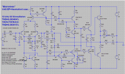
Missing conection from R2,C3 junction to GND.Maybe one of you can find the problem.
Also no connection to the anode of D4, the wire stops just short of making a connection.
I don't have the same components in my library, so I have to change components to make it run. You might want to put the device models you use into a separate text file and include that with your .asc files.
I don't have the same components in my library, so I have to change components to make it run. You might want to put the device models you use into a separate text file and include that with your .asc files.
It is true that to be loud enough and then some, not a lot of 'average' power is needed. But to be 'clean' sounding, often more power is needed just to avoid clipping
Pano's test was for determining peak power, not average.
I have scoped the output of my amplifiers numerous times and know that at my normal listening level I use very little power.
Nice work ,is this the SMD ver?
Can you tell us which software used for measurements?
Thimios.
Yeah it's the SMD version, I don't really work with through hole parts nowadays unless it's absolutely necessary. SMD tends to be more compact and you don't have to drill holes/bend and snip leads for the parts either 😀
The software is STEPS, which is a part of the ARTA package of software. The difficult part though is getting hardware good enough to give you 0.000x% results. There are a few decent sound cards that will, none are particularly cheap, but they aren't madly expensive either.
Thanks for reply.Pano's test was for determining peak power, not average.
I have scoped the output of my amplifiers numerous times and know that at my normal listening level I use very little power.
Yeah it's the SMD version, I don't really work with through hole parts nowadays unless it's absolutely necessary. SMD tends to be more compact and you don't have to drill holes/bend and snip leads for the parts either 😀
The software is STEPS, which is a part of the ARTA package of software. The difficult part though is getting hardware good enough to give you 0.000x% results. There are a few decent sound cards that will, none are particularly cheap, but they aren't madly expensive either.
Which is your sound card?
Also no connection to the anode of D4, the wire stops just short of making a connection.
I don't have the same components in my library, so I have to change components to make it run. You might want to put the device models you use into a separate text file and include that with your .asc files.
Thanks Jason and BV, it works now.
Jason, what is the easiest way to make the text file? I started to do that but it was taking forever to find the device files in the "Standard" file. You once sent me a file with the devices included right on the schematic. Is that done through the "spice directive" feature?
Thanks, Terry
Terry,
I would just open up NotePad and copy / paste from the LTspice component library and save the file as something like 'SPICE Models.txt'.
Yes, the directives in LTspice can also be the text of the required models. This embeds them so no one has to hunt for a specific model.
I would just open up NotePad and copy / paste from the LTspice component library and save the file as something like 'SPICE Models.txt'.
Yes, the directives in LTspice can also be the text of the required models. This embeds them so no one has to hunt for a specific model.
- Home
- Amplifiers
- Solid State
- Slewmaster - CFA vs. VFA "Rumble"