So don't connect G2 on the input board to anything? G2s on the output board just connect together or do they go to ground as well?
It stays within a couple volts of the raw rails but it does droop as I try to turn up the bias on the output board.
It stays within a couple volts of the raw rails but it does droop as I try to turn up the bias on the output board.
The G2s connect together with a jumper wire. The ground lug next to the output lug goes to the star ground. Thw IPS ground lug connects to the ground lug provided between PD and ND on the OPS.
The two G2s "could" go to the star rather than connecting together but that is as lot more wiring and doesn't seem to gain anything.
The two G2s "could" go to the star rather than connecting together but that is as lot more wiring and doesn't seem to gain anything.
Okay Thanks. Maybe I have some soft of ground loop going on here. I'll redo that and see what happens.
I now have two Symasui input boards and two 5 pair output board assembled. One of the output boards only has two output transistors installed. I'm getting 1.5mV on the emitter resisters of the full output board. I'm getting between 18 - 20 mV on the emitter resister of the output board with 1 pair. Both boards have around 1 mV of DC offset. I'm thinking my supply just have enough voltage to make these things work. My 45 volt 1kva transformer should arrive any day now. I'll see what it does.
My new transformer arrived. Rail voltage is much more stable now as is the 12 volt sections of the Symasui boards. I am still unable to get any bias current to flow in either of my output boards. Both Symasui boards seam to operate flawlessly standalone but when I connect them to an output board the oscillate pretty badly. I've gone completely through the components on both output boards. I've tried changing bias transistors from BD 139-16 to MJE340s. I'm at a loss where else to look.
I'd say the lack of bias adjustment is a clue. I can bias mine with +- 30V rails but my Symasui boards won't work at that voltage with the stock values. I'll see if I can simulate your issue. Please remind me what rail voltage you are running at and what values you changed in the Symasui boards. Also if you changed anything in the OPS.
I'd say the lack of bias adjustment is a clue. I can bias mine with +- 30V rails but my Symasui boards won't work at that voltage with the stock values. I'll see if I can simulate your issue. Please remind me what rail voltage you are running at and what values you changed in the Symasui boards. Also if you changed anything in the OPS.
All values are back to the schematic and 65 volt rails now.
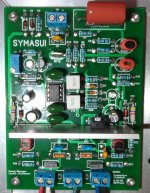
Here is a picture of a Symasui that I know works.
Looks like a few of the capacitor values on this board are different than mine.
Things like decoupling aren't critical of value, they just need to be there. I often verify with what is on hand so sometimes the values are different, but not generally where they count.
Are the two 2.2mF caps on the op amp C12 and C13 just decoupling caps? Looks like yours are .1 mF.
I'm using 15k jumpers. That's what I've been struggling with. I see no reason why bias current won't rise. I'm thinking whatever is causing that is likely causing the oscillations.
I'm just finishing a slewbaby board. Maybe my NJW0281/0302 drivers are causing grief. It uses To220s
I used NJW0281/0302 for drivers in my latest boards. They work fine. I will try to get time to take some voltage measurements. Double check all of your resistors and make sure they are all right. One one OPS board I had the wrong transistor in the cap multiplier and had a 5v drop instead of 1 1/2V. Just recheck all the TO-225 devices for proper device and orientation.
Hi guys, I'm putting the finishing touches on a CFA-XH and have a quick question.
Where is the take off point for the NFB line on the output board?
Where is the take off point for the NFB line on the output board?
jwilhelm,
You say Q107 and Q108 run hot. What do you measure across R113? What value did you use for R113? Does the bias adjuster affect the voltage reading?
You say Q107 and Q108 run hot. What do you measure across R113? What value did you use for R113? Does the bias adjuster affect the voltage reading?
Q107 and 108 run 90F. Barely warm. I had 120 ohm for R113. Just pulled it and put 150 ohm in. .75 - 1.88 volts across it from stop to stop on the bias pot
I'm playing with R103 values now. With R103 open I have 55 mV across the emitter resister and the limiter bulb is on so I'm thinking my issue is in the bias circuit itself.
- Home
- Amplifiers
- Solid State
- SlewMaster Builds