I will repeat my question..🙂
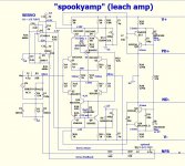
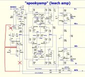
C13 and C14 are decoupling caps for the power supply to the op amp so they should go to the supply ground. The rest of them are debatable. The servo is technically suppose to keep the output of the amplifier at 0V so in theory it would make sense to reference it to the same ground the output would be using. With them connected to audio input ground they would be seeing (hopefully) a quieter ground reference point. This is one of those hands on things that testers like yourself would likely be able to figure out better than anyone else.
I hope my gibberish has helped and that the few changes work out OK.
But shame they did not remove the erroneous schematics at the time the error was first caught and at the second time some months later.
But shame they did not remove the erroneous schematics at the time the error was first caught and at the second time some months later.
I am not absolutely sure where the servo measures from.C13 and C14 are decoupling caps for the power supply to the op amp so they should go to the supply ground. The rest of them are debatable. The servo is technically suppose to keep the output of the amplifier at 0V so in theory it would make sense to reference it to the same ground the output would be using. With them connected to audio input ground they would be seeing (hopefully) a quieter ground reference point. This is one of those hands on things that testers like yourself would likely be able to figure out better than anyone else.
If the DC voltage at the signal ground is the same as the DC voltage at the power ground, then a location error for the servo would not matter. It could connect to either and both would give the same result.
But if there is a small difference in DC voltage between the Input ground/return and the output/power ground, then moving the servo measurement tapping will make a difference.
I think the servo should reference the signal input because that is the master signal that the amplifier is trying to measure and copy/scale.
However there may be a technical reason why this could be bad, even if only during some short term operating condition.
Last edited:
I hope my gibberish has helped and that the few changes work out OK.
But shame they did not remove the erroneous schematics at the time the error was first caught and at the second time some months later.
Your gibberish does help a lot for builder that can figure out all the acronyms and formulas. It's very confusing for a carpenter or plumber to understand though.
I don't think it's possible to remove incorrect schematics. There's a short time limit for editing posts. The best we can do is add an index in the first post pointing to the latest (hopefully) correct info which Ostripper has done in the main thread, but most haven't noticed.
I am sure the Moderating team would find a way, if they wanted to ensure that the Forum does not contain proven erroneous schematics, unless there were an educational value in maintaining some as examples that are explained in some accompanying posts.
I do hope the use of that word does have any consequences.
I do hope the use of that word does have any consequences.
C13 and C14 are decoupling caps for the power supply to the op amp so they should go to the supply ground. The rest of them are debatable. The servo is technically suppose to keep the output of the amplifier at 0V so in theory it would make sense to reference it to the same ground the output would be using. With them connected to audio input ground they would be seeing (hopefully) a quieter ground reference point. This is one of those hands on things that testers like yourself would likely be able to figure out better than anyone else.
Yes,thanks Jeff,you remind me that question already answered by me in the main thread long time ago.
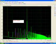
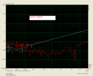
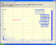
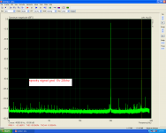
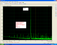
To be more clear i will split the results in two section.
1st.the original circuit and the results.
Attachments
Last edited:
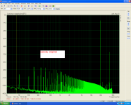
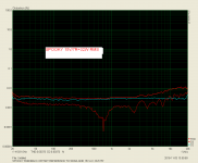
2nd the improvement version and the results.
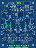
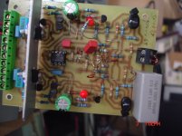
4 parts lifted from power gnd and connected to signal gnd(see the real pcb).
4 parts lifted from power gnd and connected to signal gnd(see the real pcb).
Attachments
Last edited:
It would be interesting to see if the big change came from moving the servo ground or the feedback ground. Is it possible to repeat testing with the servo ground connected to supply ground?
This will end up in disappointment normally. If you want to be successful you will need to plan much more before this point. I build my own chassis from scratch which has many advantages as well, but does consume a lot of time.
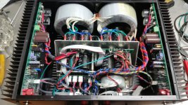
In my NS series builds for example I took the time to design everything before hand. This is a dual monoblock design sharing a single chassis.I was planning to make these a rack mount design. First I designed transformer mounts into the inside of the front cover so the bulk of the weight was hanging on the rack to minimize stress on the chassis. The usual culprit for stray EMF from a toroidal transformer is at the wire connections so I mounted them top and bottom. The most logical place to run mains power was down the center of the bottom of the chassis.
I designed the supplies to stand vertically directly behind the transformers with the AC connections at the top 1" away from the transformers. I designed the supplies to be a dual board mounted with the bottom sides facing each other and had the rail connections again at the top in the middle of the chassis. I stacked the control board, power relays onto the supply module and made the whole mains ac wiring flow down the lower center of the amp to a mains inlet in the lower center of the rear cover. I also designed this whole power supply module to lift out of the chassis by removing four screws in the bottom cover making it very compact, but also very easy to service.
Next I laid out the amplifier boards so the noisy output section was at the front towards the supplies and transformer and the input section was at the rear top outward extreme of the chassis as far away as possible from the mains wiring. Input RCA connectors were board mounted poking through the rear cover to eliminate any internal signal wiring.
A layout like this minimized excess wiring and minimizes the possibility of inducing noise into the amplifiers. This is not possible to do by putting together a bunch of boards on the bench and cramming them together. This take a lot of planning and measurement before even beginning and careful planning even before purchasing the first part, eg. you need to select transformers and supply caps that will fit the application before beginning. PC boards should be laid out for the application as well. In this case there are a left channel and a right channel board and it all fits nicely in a fairly compact chassis. It can be configure to be a 200W+ amplifier comfortably in less space than a lot of 50W amps shown in the forums with less noise issues.
Do have a picture to share of the final results? Thanks
After reading all of this, WHY was a TL072 (a dual opamp) was specified and only using half. This is not a good choice as a servo. A TL071 would be a better choise as you can zero offset. I intend to use a OPA134. Has anyone else used an OPA134? There should be some test point to adjust out the offset and a specified procedure or else sort the OPAMP before you install it. RAY HUGHES
Would it make a better servo if you hooked the dual opamp up as an instrumentation amplifier? Thanks, Ray
After reading all of this, WHY was a TL072 (a dual opamp) was specified and only using half. This is not a good choice as a servo. A TL071 would be a better choise as you can zero offset. I intend to use a OPA134. Has anyone else used an OPA134? There should be some test point to adjust out the offset and a specified procedure or else sort the OPAMP before you install it. RAY HUGHES
Pete chose a simple cheap op amp that was more likely for everyone to have kicking around. 2-3mV drift wasn't really a concern for him. OPA134 won't fit the footprint in the layout from the group buy.
Here's an internal picture of an earlier prototype. They've gotten neater since but I've never snapped a picture of a newer one. 17" x 13" x 6" chassis with 220W output. The heatsinks run a little warm ~55 - 60C with 75V rails.
Is that 220w each channel at 8 ohms? What is the part number of those transformers, I am at the ready to build with the same basic specs...Thanks
Is that 220w each channel at 8 ohms? What is the part number of those transformers, I am at the ready to build with the same basic specs...Thanks
Yes that one was 220W/ channel. AS-4450 - 400VA 50V Transformer - AnTek Products Corp If you plan to use Aux windings in the Antek transformers you need to be careful. Some are listed as 15/15VAC but are actually 12/18VAC when you open the box. I had to jump through hoops for 8 months last year to get them to replace a few for me.
Second Spooky IPS tested today. With 3,8 mA through R12/13 I got 5.7 mA trough the 100 ohm test resistors. I think this is fine. The second OPS need output trasistors to be mounted before a full test. LF 412 gave a very fine offset result.
Eivind S
Eivind S
Pete chose a simple cheap op amp that was more likely for everyone to have kicking around. 2-3mV drift wasn't really a concern for him. OPA134 won't fit the footprint in the layout from the group buy.
The OPA2134 will fit will it not? Ray
Hmm
I built the Spooky per the schematic that AndrewT is calling wrong and it played perfectly.
I built the Spooky per the schematic that AndrewT is calling wrong and it played perfectly.
Nice!Here's an internal picture of an earlier prototype. They've gotten neater since but I've never snapped a picture of a newer one. 17" x 13" x 6" chassis with 220W output. The heatsinks run a little warm ~55 - 60C with 75V rails.
I guess the new one is perfect😎
- Home
- Amplifiers
- Solid State
- SlewMaster Builds