1.Like Vrystaat I find this last posts very confusing. Why cant Andrew came up with correct DRAWING on a the same schema shown in post 2078 like what Vrystaat tried to do.
2. This go to Jkueterman: The lay out you show in post 2069, is this correct according to the ground connection we now discuss? If the lay out need to be corrected, can you please, with a DRAWING, show us what to do. Words only often lead to more confusion.
3. If Andrew is correct about C11, let us have OS (or others) on the "plane". And if C11 is incorrect placed, let us know what to do.
Eivind S
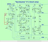
I think this is what AndrewT is trying to say is the correct input ground connection.
I recall Ostripper mentioning the 4.7R value for R3 being needed to make the servo operate correctly. I'm on the fence as to which connection to ground is correct for the servo. Technically we want the amplifier output to be close to zero volts referenced to the output, not referenced to input. Both really should be very close to the same unless there's an issue with the input or wiring though.
I recall Ostripper mentioning the 4.7R value for R3 being needed to make the servo operate correctly. I'm on the fence as to which connection to ground is correct for the servo. Technically we want the amplifier output to be close to zero volts referenced to the output, not referenced to input. Both really should be very close to the same unless there's an issue with the input or wiring though.
Attachments
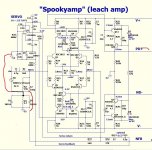
This is how the Vin connection is configured on Ver 1.3 and V2. Surely this must be correct.😕
Last edited:
1.Like Vrystaat I find this last posts very confusing. Why cant Andrew came up with correct DRAWING on a the same schema shown in post 2078 like what Vrystaat tried to do.
2. This go to Jkueterman: The lay out you show in post 2069, is this correct according to the ground connection we now discuss? If the lay out need to be corrected, can you please, with a DRAWING, show us what to do. Words only often lead to more confusion.
3. If Andrew is correct about C11, let us have OS (or others) on the "plane". And if C11 is incorrect placed, let us know what to do.
Eivind S
Jason's layout has the input ground connected correctly. The servo reference ground C11 is connected to the main ground which should make the output of the amplifier zero volts referenced to the output ground.
You won't likely hear much from Ostripper on this. He's still on his cross country bike tour.
post2082I think this is what AndrewT is trying to say is the correct input ground connection.
I recall Ostripper mentioning the 4.7R value for R3 being needed to make the servo operate correctly. I'm on the fence as to which connection to ground is correct for the servo. Technically we want the amplifier output to be close to zero volts referenced to the output, not referenced to input. Both really should be very close to the same unless there's an issue with the input or wiring though.
YES !!!
Vin is now connected to the input.
The NFB is now measuring from the input.
The servo is now measuring from the input.
The Power Ground is now separated from the signal side.
One last item that needs to be checked while setting up the working and tested amplifier.
What is the DC voltage drop across the Sig to Power ground voltage reference resistor? Vr3 in post2082
If it is not zero mVdc then that tells you that the two supply rails currents are not the same.
Make them the same !!!!!!
Then the output offset voltage measured at the OUTPUT is the same as when measured to the Sig Ground.
There is a small AC current flowing through this voltage reference link, but it is tiny. There will be a small interference current flowing through as well, but again it should be tiny. But there should not be a DC current passing.
The Signal ground SHOULD be at the same voltage as the Output Ground.
The is the WHOLE purpose of the voltage reference link between INPUT and OUTPUT. These two voltages should be the same.
Last edited:
This is how the Vin connection is configured on Ver 1.3 and V2. Surely this must be correct.😕
D1, D2 and R3 are there to add a little separation between the main supply ground and the input ground. This acts as a ground loop breaker among other things. Audio input ground should be connected through it.
Pete's schematics are pictures of his simulation files. He will connect things differently than real world connections for simulations. I suspect he just forgot to change this connection back before sharing. Notice the two lines on either side of C1. This would normally be shorted during simulation as well.
Maybe because I did not design this amp, nor have I biuilt this amp, nor have I got the PCBs for this amp.Why cant Andrew came up with correct DRAWING on a the same schema shown in post 2078 like what Vrystaat tried to do.
Surely it is the responsibility of the Builders to research their project and sort out the problems before they start assembly.
It is some years since most of these sch were published.
Doubts about connections should have been sorted years ago.
If any slip through unnoticed, but get caught at some later date, then that was the time to sort it and get all the erroneous sch removed. That is the responsibility of those Members that were actively pursuing that project at that time.
It should not take a casual reading years later to pick up these same errors again.
The basic problem was that the erroneous sch were not removed!
Last edited:
Like this then on Ver 1.2🙂. Thanks a lot guy's now I have some speed again. The Kypton ND has a 10R resistor there which caused noise. I jumpered it and thereafter the amp were quiet.
The Kypton ND has a 10R resistor there which caused noise. I jumpered it and thereafter the amp were quiet.Attachments
Last edited:
post2088 sch
Yes. Remove the surplus G2 symbol.
But why the noise. that sounds like a different problem with the wrong solution.
Have a look at C2 (and all the other sch as well).
It is an RC filter for interference above the audio passband.
F-3dB ~ = 1/{2 Pi R C} which comes out at 1M9Hz
That is far too high, some will choose 300kHz, some will choose 200kHz and a few might even choose 100kHz.
Anything >=500kHz is too high !
If I were building this I would make C2 = 1n5F and add a 47pF across the input socket. Catch the WiFi and mobile phone interference BEFORE it gets onto the internal cabling.
Last edited:
Maybe because I did not design this amp, nor have I biuilt this amp, nor have I got the PCBs for this amp.
Surely it is the responsibility of the Builders to research their project and sort out the problems before they start assembly.
He's just asking you to say what you mean more clearly, like the little drawing I made. This makes it much easier for people to understand. It's tough for a hobbyist to interpret a bunch of acronyms, ect The old saying a picture is worth a thousand words...
There are different ways for people to learn. Some can spend months reading and researching every aspect of a project, then begin. Other roll up their sleeve, dig in and actually do something, then learn from their mistakes. Spending months with your nose in books almost always leads to a very poor finished product. All the minute technical stuff will be correct, but usually the blatantly obvious stuff is wrong.
Builders are supposed to be the hardware guys. They should be spending their time planning out their build, not redesigning the amplifier. It's easy to take the most technically perfect amplifier and make it into a piece of junk by putting it into a chassis incorrectly. It's also easy to take a simple amplifier and make it excellent by planning and installing parts correctly. In my opinion there's where builders should be spending their time researching but it's not something you learn from a book.
Last edited:
Just as a reminder.
All interconnections require a TWO WIRE connection.
Get ALL those interconnections done first.
Then look to see what other connections are missing from the sch. that's when you notice that the voltage reference between Input and Ouput needs to be added.
Next:
The amplifier MEASURES the differential voltage at the input socket.
It process that voltage difference and sends a scaled copy to the Output as a voltage difference.
Any processing internally has to use the INPUT SIGNAL as the master. That input signal is what the amplifier is trying to copy.
I don't agree with any of your argument.He's just asking you to say what you mean more clearly, like the little drawing I made. This makes it much easier for people to understand. It's tough for a hobbyist to interpret a bunch of acronyms, ect The old saying a picture is worth a thousand words...
There are different ways for people to learn. Some can spend months reading and researching every aspect of a project, then begin. Other roll up their sleeve, dig in and actually do something, then learn from their mistakes. Spending months with your nose in books almost always leads to a very poor finished product. All the minute technical stuff will be correct, but usually the blatantly obvious stuff is wrong.
Builders are supposed to be the hardware guys. They should be spending their time planning out their build, not redesigning the amplifier. It's easy to take the most technically perfect amplifier and make it into a piece of junk by putting it into a chassis incorrectly. It's also easy to take a simple amplifier and make it excellent by planning and installing parts correctly. In my opinion there's where builders should be spending their time researching but it's not something you learn from a book.
It is the Builder's responsibility to research their chosen project.
It is not my responsibility to point out the same errors being repeated year after year.
Yet when I see dubious info, I feel compelled to not allow Builders to adopt erroneous build information.
I am going to spend a little time on your last statement.In my opinion there's where builders should be spending their time researching but it's not something you learn from a book.
Much of this building can be learned from reading the correct books.
Alternatively, much of this build learning can be from reading this Forum, if you know how to sort the wheat from the chaff.
Nothing is learned from cobbling together a pile of component and getting a product that does not work.
Sorting it out from reading advice after the fact will probably be a big learning.
But the build mistake could be avoided by reading and copying what was done CORRECTLY before by other Builders.
One learns nothing from a mistake other than one has the wrong answer.
It is the comparing of the wrong with the right that gives the learning.
One learns from getting it right. And better to do that first time.
It is the Builder's responsibility to research their project. That takes time.
Too many Members are en-awed by other Members that bang out projects on an almost daily basis.
With the result they think it is good to do the same.
Last edited:
I don't agree with any of your argument.
It is the Builder's responsibility to research their chosen project.
It is not my responsibility to point out the same errors being repeated year after year.
Yet when I see dubious info, I feel compelled to not allow Builders to adopt erroneous build information.
I'm not surprised you disagree with common sense. This goes along with having your nose in a book and never actually doing anything.
Nobody said it's your responsibility to do anything. They just asked if you want to be helpful to actually put things in English and black and white, not some gibberish.
I am going to spend a little time on your last statement.
Much of this building can be learned from reading the correct books.
Alternatively, much of this build learning can be from reading this Forum, if you know how to sort the wheat from the chaff.
Nothing is learned from cobbling together a pile of component and getting a product that does not work.
Sorting it out from reading advice after the fact will probably be a big learning.
But the build mistake could be avoided by reading and copying what was done CORRECTLY before by other Builders.
One learns nothing from a mistake other than one has the wrong answer.
It is the comparing of the wrong with the right that gives the learning.
One learns from getting it right. And better to do that first time.
One of the most important steps is to actually draw all the parts and fit them into the box before you start to drill holes. This is nothing you will find in a book. Looking at pictures in the forum can lead you astray quickly too. There are a lot of bad examples to look at. Flip and flop all the parts to get the best fit and wire routing. This is probably the biggest downfall to most builds. This is why you see a huge chassis with nothing in it and it still is noisy. 3D software is good for this but very time consuming. I do this in Corel Draw 2D software to save time. My whole amplifier is normally designed before I even send files to the board house. There are far fewer problems this way.
Yes reading the aftermath of previous builds is also very valuable info. This doesn't involve redesigning the amplifier from scratch unless it's a complete disaster though.
Jwilhelm, thank you for pointing out this:
"He's just asking you to say what you mean more clearly, like the little drawing I made. This makes it much easier for people to understand. It's tough for a hobbyist to interpret a bunch of acronyms, ect The old saying a picture is worth a thousand words...
There are different ways for people to learn. Some can spend months reading and researching every aspect of a project, then begin. Other roll up their sleeve, dig in and actually do something, then learn from their mistakes. Spending months with your nose in books almost always leads to a very poor finished product. All the minute technical stuff will be correct, but usually the blatantly obvious stuff is wrong.
Builders are supposed to be the hardware guys. They should be spending their time planning out their build, not redesigning the amplifier. It's easy to take the most technically perfect amplifier and make it into a piece of junk by putting it into a chassis incorrectly. It's also easy to take a simple amplifier and make it excellent by planning and installing parts correctly. In my opinion there's where builders should be spending their time researching but it's not something you learn from a book".
Everyone that use diyAudio for inspiration and help cant be experts. Trying to explain that for Andrew is totally useless. His ears listen only to his own. I have more than once
recieved answers from him filled with arrogance.
Eivind S
Yet I have described that in this Forum many times.One of the most important steps is to actually draw all the parts and fit them into the box before you start to drill holes. This is nothing you will find in a book................
Get the assembly working on the bench.
Fold it up into the shape that will suit a box.
Check that performance has not deteriorated.
Then buy a box to suit that final shape.
The holes get drilled AFTER the performance of the final shape/folding has been checked.
I will repeat my question..🙂c11,c13 c14, D9,D10 connection to power gnd is ok?
Yet I have described that in this Forum many times.
Get the assembly working on the bench.
Fold it up into the shape that will suit a box.
Check that performance has not deteriorated.
Then buy a box to suit that final shape.
The holes get drilled AFTER the performance of the final shape/folding has been checked.
This will end up in disappointment normally. If you want to be successful you will need to plan much more before this point. I build my own chassis from scratch which has many advantages as well, but does consume a lot of time.
In my NS series builds for example I took the time to design everything before hand. This is a dual monoblock design sharing a single chassis.I was planning to make these a rack mount design. First I designed transformer mounts into the inside of the front cover so the bulk of the weight was hanging on the rack to minimize stress on the chassis. The usual culprit for stray EMF from a toroidal transformer is at the wire connections so I mounted them top and bottom. The most logical place to run mains power was down the center of the bottom of the chassis.
I designed the supplies to stand vertically directly behind the transformers with the AC connections at the top 1" away from the transformers. I designed the supplies to be a dual board mounted with the bottom sides facing each other and had the rail connections again at the top in the middle of the chassis. I stacked the control board, power relays onto the supply module and made the whole mains ac wiring flow down the lower center of the amp to a mains inlet in the lower center of the rear cover. I also designed this whole power supply module to lift out of the chassis by removing four screws in the bottom cover making it very compact, but also very easy to service.
Next I laid out the amplifier boards so the noisy output section was at the front towards the supplies and transformer and the input section was at the rear top outward extreme of the chassis as far away as possible from the mains wiring. Input RCA connectors were board mounted poking through the rear cover to eliminate any internal signal wiring.
A layout like this minimized excess wiring and minimizes the possibility of inducing noise into the amplifiers. This is not possible to do by putting together a bunch of boards on the bench and cramming them together. This take a lot of planning and measurement before even beginning and careful planning even before purchasing the first part, eg. you need to select transformers and supply caps that will fit the application before beginning. PC boards should be laid out for the application as well. In this case there are a left channel and a right channel board and it all fits nicely in a fairly compact chassis. It can be configure to be a 200W+ amplifier comfortably in less space than a lot of 50W amps shown in the forums with less noise issues.
- Home
- Amplifiers
- Solid State
- SlewMaster Builds