Thanks for all advices about a replacement for TL 072.
Does anyone have a comment to my measurement? I remember from my build with Kypton IPS, the voltage measurement between ND- and PD+ should be 11-12 V. On my Spooky I measured only one tenth of that: 1.2V. The mesaurement was taken with the 10 ohm connected to the NFB point. What is the correct value here for the Spooky??
In post 2035 both V has fallen out and a 0 . I measured 0.61V over the 100 ohm resistors.
0.61/100=0.006. This means 6mA through this resistors.
jkueterman, where are you? You are the man behind my Spooky PCB.
Eivind S
Last edited:
OP07, OP77, OP90 are also good, cheap choices.
Well, in general, almost any OpAmp can be used as a servo, but then you have to take in account some things, like the input currents - all these have got BJTs at their inputs.
LF411/LF412 have got jFETs at the input, having virtually no input currents, allowing higher R and lower C in the integrator.
Thanks for all advices about a replacement for TL 072.
Does anyone have a comment to my measurement? I remember from my build with Kypton IPS, the voltage measurement between ND- and PD+ should be 11-12 V. On my Spooky I measured only one tenth of that: 1.2V. The mesaurement was taken with the 10 ohm connected to the NFB point. What is the correct value here for the Spooky??
In post 2035 both V has fallen out and a 0 . I measured 0.61V over the 100 ohm resistors.
0.61/100=0.006. This means 6mA through this resistors.
jkueterman, where are you? You are the man behind my Spooky PCB.
Eivind S
Eivind, measurements with the resistors (standalone IPS testing) and with OPS (normal operation) are completely different stories.
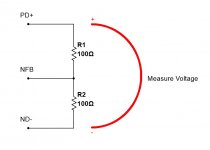
You normally connect 2 resistors from PD+ and ND- to NFB point (treating NFB point as output in this case) only for making sure the front-end board runs fine and see that the offset is close to zero and measure the VAS idle current.
For more precise measurement of the VAS idle current (assuming the frint-end is VFA with relatively high impedance NFB network, like Spooky), I recommend using 100R resistors, measuring the voltage over both of them in series - see attached.
What do you see in this case?
Attachments
Isn't TL071/72 also jFET?Well, in general, almost any OpAmp can be used as a servo, but then you have to take in account some things, like the input currents - all these have got BJTs at their inputs.
LF411/LF412 have got jFETs at the input, having virtually no input currents, allowing higher R and lower C in the integrator.
Isn't TL071/72 also jFET?
Terry, you're right - those ones are also have jFETs at the inputs. They are pretty good for audio applications (when they are on the signal path - like in the line stage or something), by the way. However, their default offset will be higher, although it may be trimmed, as shown in the datasheet. Well, in most cases, offset within a few mV is no problem anyway.
LF411A/LF412A are internally compensated for low offset and low drift - those are the OpAmps, designed with the focus on instrumentation applications (DC servo is one of them). They provide the offset within 0.5mV, that can also be trimmed further on (well, no need to trim for servo in the audio amp - already good as is). A "fire and forget" sort of thing 🙂
Last edited:
vzaichenko
In post 2035 I wrote:"Today I fired up the IPS with 100 ohm connected to NFB and ND-/PD+. I measured 0.61V over 100 ohm. Over R12/R13 I could easily set 3.8 mA. Offset a dissapointing 50 mV with a TL 072 connected".
0.61V over 100 ohm gives 6mA trough the 100 ohm resistors.
The measured 3.8mA over R12 and R13 is also according to schema. It is what voltage I measured between ND- and PD+ that I find confusing (1.2V) according to what jwilhelm wrote in his start up prosess on Kypton: "After that set, measure the voltage between PD+ and ND-. You should read around 11V if everything is working right".
My measurement 0.6V x2= 1.2V (over both 100ohm) must be correct. May be jwilhelm have used 1K resistors when he came up with a result of 11V.
Eivind S
Last edited:
vzaichenko
In post 2035 I wrote:"Today I fired up the IPS with 100 ohm connected to NFB and ND-/PD+. I measured 0.61V over 100 ohm. Over R12/R13 I could easily set 3.8 mA. Offset a dissapointing 50 mV with a TL 072 connected".
0.61V over 100 ohm gives 6mA trough the 100 ohm resistors.
The measured 3.8mA over R12 and R13 is also according to schema. It is what voltage I measured between ND- and PD+ that I find confusing (1.2V).
Eivind S
Well, that's fine - if you measure 0.6V across 100R, you measure 1.2V across 200R - that's what you have between PD+ and ND-, right?
As soon as you connect a real OPS instead of two resistors, you will see higher voltage (having the same VAS idle current), as impedance of OPS's bias spreader is higher than 200R.
Cheers,
Valery
All of these are BJT input. BJT input do not make good DC servo opamps.OP07, OP77, OP90 are also good, cheap choices.
Use jFET input opamps for DC servo duty.
If I recall correctly my chart was written using 1K resistors to measure VAS. 6mA is the correct VAS idle current.vzaichenko
In post 2035 I wrote:"Today I fired up the IPS with 100 ohm connected to NFB and ND-/PD+. I measured 0.61V over 100 ohm. Over R12/R13 I could easily set 3.8 mA. Offset a dissapointing 50 mV with a TL 072 connected".
0.61V over 100 ohm gives 6mA trough the 100 ohm resistors.
The measured 3.8mA over R12 and R13 is also according to schema. It is what voltage I measured between ND- and PD+ that I find confusing (1.2V) according to what jwilhelm wrote in his start up prosess on Kypton: "After that set, measure the voltage between PD+ and ND-. You should read around 11V if everything is working right".
My measurement 0.6V x2= 1.2V (over both 100ohm) must be correct. May be jwilhelm have used 1K resistors when he came up with a result of 11V.
Eivind S
New measurement:
Over R25: 8.1mA
Over R29: 8.8mA
Schema say 7.5mA
Any changes recommended, or it is close enough to connect IPS to OPS?
Eivind S
Over R25: 8.1mA
Over R29: 8.8mA
Schema say 7.5mA
Any changes recommended, or it is close enough to connect IPS to OPS?
Eivind S
Quoted below are the testing tips for the Spooky, posted by one of our veterans. I used the same for my build.
Fire up the input stages with their outputs disconnected from the output board and 1k resistors jumpered from PD+ to the NFB connection and from ND- to the NFB connection. Measure the voltage drop across R12. Adjust R19 so this is 3.8mA (3.8V). do the same with R13 and R10. After that's set, measure the voltage between PD+ and ND-. You should read around 11V if everything is working right. Also measure the DC offset at the NFB connection. I do this with the servo pulled out first just to see how good the input is matched, then with the servo in place. With the servo installed, there shouldn't be more than around 25mV present. If everything is well matched, it will be drifting around 2 or 3 mV.
Fire up the input stages with their outputs disconnected from the output board and 1k resistors jumpered from PD+ to the NFB connection and from ND- to the NFB connection. Measure the voltage drop across R12. Adjust R19 so this is 3.8mA (3.8V). do the same with R13 and R10. After that's set, measure the voltage between PD+ and ND-. You should read around 11V if everything is working right. Also measure the DC offset at the NFB connection. I do this with the servo pulled out first just to see how good the input is matched, then with the servo in place. With the servo installed, there shouldn't be more than around 25mV present. If everything is well matched, it will be drifting around 2 or 3 mV.
I know this very well It is jwilhelms chart for firing up Spooky IPS. I have followed this and a simular chart when I fired up my Kypton.
I will wait for comments om my last measurement over R25(8.1mA) andR29(8.8mA) before I connect to OPS.
Eivind S
I will wait for comments om my last measurement over R25(8.1mA) andR29(8.8mA) before I connect to OPS.
Eivind S
Did you match the input transistors for he?
Did you match the input transistors for hfe (collector current)? Ray
I know this very well It is jwilhelms chart for firing up Spooky IPS. I have followed this and a simular chart when I fired up my Kypton.
I will wait for comments om my last measurement over R25(8.1mA) andR29(8.8mA) before I connect to OPS.
Eivind S
Did you match the input transistors for hfe (collector current)? Ray
Can you measure the voltage over R14,R16,R15,R17 & R8,R9,R20,R21 & the zeners & D3,D4 , D7,D8.
R25(8.1mA) andR29(8.8mA) (you mean R31 8.8mA)
You should have near same voltage drop over those R25,R31 . You can adjust the 3.8mA over R12,R13
smaller it will drop the voltage over R25,R31 depending on how much the led D3,D4 voltage drop is.
I have voltage over R14,R16,R15,R17 84.5mV-85mV over R25-R31 7.6mA
R8,R9,R20,R21 1.75V-1.76V
If you need more data . Ask .
Goodnight BR.toni
Anyway, at 6mA VAS idle current it's ok to connect the OPS and test the amp as a whole. Just make sure to set the bias trimmer in OPS to minimum bias position for safe first power-on.
grhughes
No, I have not matched small signal tansistors on my IPS. According to OS the servo should be able handle a "high" mismatch. If you are up to match, Q1/Q2 is the most important pair to match(ref. OS)
tonza75
Your measuring are very usefull. My power is +/-67V DC, what is yours?
vzaichenko you wrote: "Just make sure to set the bias trimmer in OPS to minimum bias position for safe first power-on".
Shall I set R106 to zero(0 ohm) or to 200 ohm for start up?
My 8.1 mA and 8.8 mA over 150 ohm(R25/R31) have no important influence, and can be as is?
Eivind S
grhughes
No, I have not matched small signal tansistors on my IPS. According to OS the servo should be able handle a "high" mismatch. If you are up to match, Q1/Q2 is the most important pair to match(ref. OS)
tonza75
Your measuring are very usefull. My power is +/-67V DC, what is yours?
vzaichenko you wrote: "Just make sure to set the bias trimmer in OPS to minimum bias position for safe first power-on".
Shall I set R106 to zero(0 ohm) or to 200 ohm for start up?
My 8.1 mA and 8.8 mA over 150 ohm(R25/R31) have no important influence, and can be as is?
Eivind S
R106 must be in the max ohm position (200 ohm). The higher R -> the lower the bias.
8.1 mA and 8.8mA over R25/R31 is fine - those currents are always higher than VAS idle current in Hawksford cascode, as part of the current, flowing through those resistors, goes to the LEDs.
Cheers,
Valery
A little help with the Spooky plse.
I do not have KSC 1815(NPN, 45V, 100mA) and KSA 1015(PNP, 50V,150mA).
Can I use BC 550C (NPN, 50V,100mA ) and BC560C (PNP,45V, 100mA) as replacement ?
OS used the BCXXX transistors in a latter Spooky version. He also changed the 47R resistors to 68R if I remember correctly. They are not pin to pin compatible. You have to twist them around....
- Home
- Amplifiers
- Solid State
- SlewMaster Builds