Once I finish my Badger, I think a Slewmaster Plate amp will be next on my project list. This thread is awesome! I love to follow the builds!
Updated BOMs
Here are the spreadsheets I made when I was assembling my amplifier.
I have posted some of these before. However, I made a few corrections and cleanups since then.
The only glaring mistake in the older versions is Rsl being included in the Spooky BOM. I have tried it for myself, and while the servo settles slightly faster. It also causes more offset. I got 90mV offset vs 1mV without Rsl. I left the Rsl in the Symasui BOM where it is still needed.
Some of the transistors and resistors are different than the original schematic, they are just what I chose to use. I used KSC2690/KSA1220 for the capacitance multiplier because they are highest gain TO-126 transistors I had in my parts bins.
Attachments
Last edited:
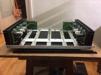
Final assembly and testing
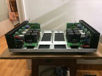
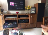
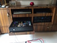
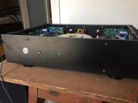
All the bits and pieces have gone in finally. The amp is on endurance test, monitoring the bias continuously. Sounds great, with no glitches so far.
Hari
All the bits and pieces have gone in finally. The amp is on endurance test, monitoring the bias continuously. Sounds great, with no glitches so far.
Hari
Attachments
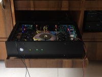
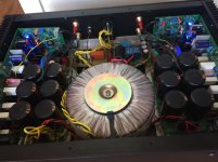

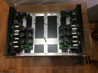
Is that a centre tapped secondary supplying two rectifiers and two separated capacitor banks?
Your amp turned out well! You definitely have excellent layout skills, I wouldn't have been able to fit an over 150W amp in such a relatively small enclosure.
Is that a centre tapped secondary supplying two rectifiers and two separated capacitor banks?
That's correct.
Your amp turned out well! You definitely have excellent layout skills, I wouldn't have been able to fit an over 150W amp in such a relatively small enclosure.
Thanks akimmet. I do a lot of fabrication with aluminium. This enclosure was built around the 100mmX300mmX25mm heatsinks. Did quite a lot of simulation with cardboard templates before finalising the enclosure. Mind you, I had to test the amp extensively and be 200% sure everything's working before sticking them in!!
Hari
Is that a centre tapped secondary supplying two rectifiers and two separated capacitor banks?
you must be careful to avoid creating a loop between the two amplifiers.That's correct.
At present there is a common Zero volts connecting the two amplifier together via the zero volts that starts at the centre tap and goes through both PSUs to both amplifiers.
one pair of BJT output devices rated at 180W each, allows a reliable maximum output of 75W.I am planning a slewmaster mini ops using one pair (bjt) output as per the schematic below. I would like to know what is the optimum supply voltage for this for driving an 8 ohm load. Thanks.
Hari
You can hit that target into 8ohms using a 30-0-30Vac, or 32-0-32Vac transformer rated at 150VA to 300VA for a stereo amplifier.
Expect to be able to carry out short term testing at full power (unclipped) into 4r0 resistive dummy load to ~32Vpk for a couple of seconds (the heatsink must remain cold during this test).
you must be careful to avoid creating a loop between the two amplifiers.
At present there is a common Zero volts connecting the two amplifier together via the zero volts that starts at the centre tap and goes through both PSUs to both amplifiers.
I am not having any problems with ground loops as of now. I have used this config on my earlier builds also (quasi-complementary) with no loop issues.
Hari
one pair of BJT output devices rated at 180W each, allows a reliable maximum output of 75W.
You can hit that target into 8ohms using a 30-0-30Vac, or 32-0-32Vac transformer rated at 150VA to 300VA for a stereo amplifier.
Expect to be able to carry out short term testing at full power (unclipped) into 4r0 resistive dummy load to ~32Vpk for a couple of seconds (the heatsink must remain cold during this test).
Thanks Andrew. I will then settle for 20-0-25 VAC considering the 100mmX150mmX27mm heatsinks (1.25°C/W) that I will be using.
Hari
25-0-25Vac should allow about 50W into 8ohms.
I was given a pair of speakers to dispose of. I opened up that Mission 8ohms rated speaker yesterday.
It has a bass driver that measures 3r6 and a treble driver that measures 5r1 with a 1r0 dropping resistor in series.
That makes it effectively a 4 to 8ohms speaker.
The majority of the power is delivered into an effective 5ohms speaker load.
Mission told lies !
Hi Guys
I have my amplifier with two 2 pair slewmaster boards, but my driver heatsink get ver hot to tuch after few Hours the amplifier has been turned on.
It need a better way for the heat to get away from the driver heatsink.
PSU is 50+-v resister R113 = 120 ohm
What can i do to solve this?
http://
I have my amplifier with two 2 pair slewmaster boards, but my driver heatsink get ver hot to tuch after few Hours the amplifier has been turned on.
It need a better way for the heat to get away from the driver heatsink.
PSU is 50+-v resister R113 = 120 ohm
What can i do to solve this?
http://
An externally hosted image should be here but it was not working when we last tested it.
Last edited:
Kimschips, the driver heatsink should never get so hot. Have you set the offset and bias correctly. Follow the adjustment steps as given in one of the earlier posts. I followed those steps and the amp is working perfectly. The driver heatsink is not even warm to touch.
Hari
Hari
Kimschips, the driver heatsink should never get so hot. Have you set the offset and bias correctly. Follow the adjustment steps as given in one of the earlier posts. I followed those steps and the amp is working perfectly. The driver heatsink is not even warm to touch.
Hari
Thanks can i also ask you these:
What is your Psu voltages and what value do you have for R113?
Yes my offset is close to zero and bias set for +÷75mA though each output pair.
Where can i find the adjustment procedure?
Measure and post results.
Start by measuring the Vdrop across each driver, Vce,
then measure the Vdrop across each output, Vce
then measure the Vdrop across the driver's emitter resistor, Vre
then measure the Vdrop across the outputs' emitter resistors, Vre
is not a measurement.get ver hot to tuch after few Hours
Start by measuring the Vdrop across each driver, Vce,
then measure the Vdrop across each output, Vce
then measure the Vdrop across the driver's emitter resistor, Vre
then measure the Vdrop across the outputs' emitter resistors, Vre
- Home
- Amplifiers
- Solid State
- SlewMaster Builds