Yes, the tweeter doesn't need that much space in front of or at the back of the membrane as it doesn't move that much in those directions.
I just mount the membrane closer to the front pole pieces then.
Maybe the reflections will move upwards in frequency as well.
I just mount the membrane closer to the front pole pieces then.
Maybe the reflections will move upwards in frequency as well.
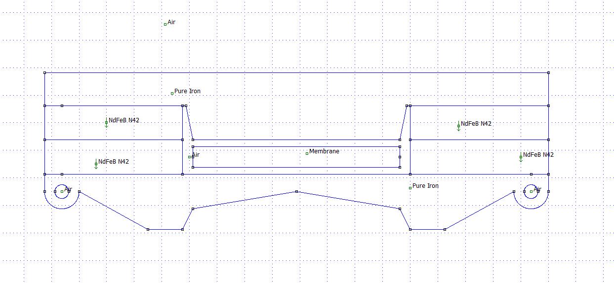
Tweeter part
Something like this then:
Membrane is not so deep and moved closer to the front pole piece.
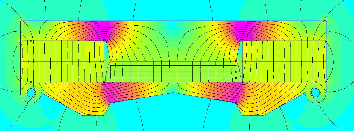
Yes, definitely stronger flux.
I hope I can mount it 😱.
😱.
Something like this then:
An externally hosted image should be here but it was not working when we last tested it.
Membrane is not so deep and moved closer to the front pole piece.
An externally hosted image should be here but it was not working when we last tested it.
An externally hosted image should be here but it was not working when we last tested it.
Yes, definitely stronger flux.
I hope I can mount it
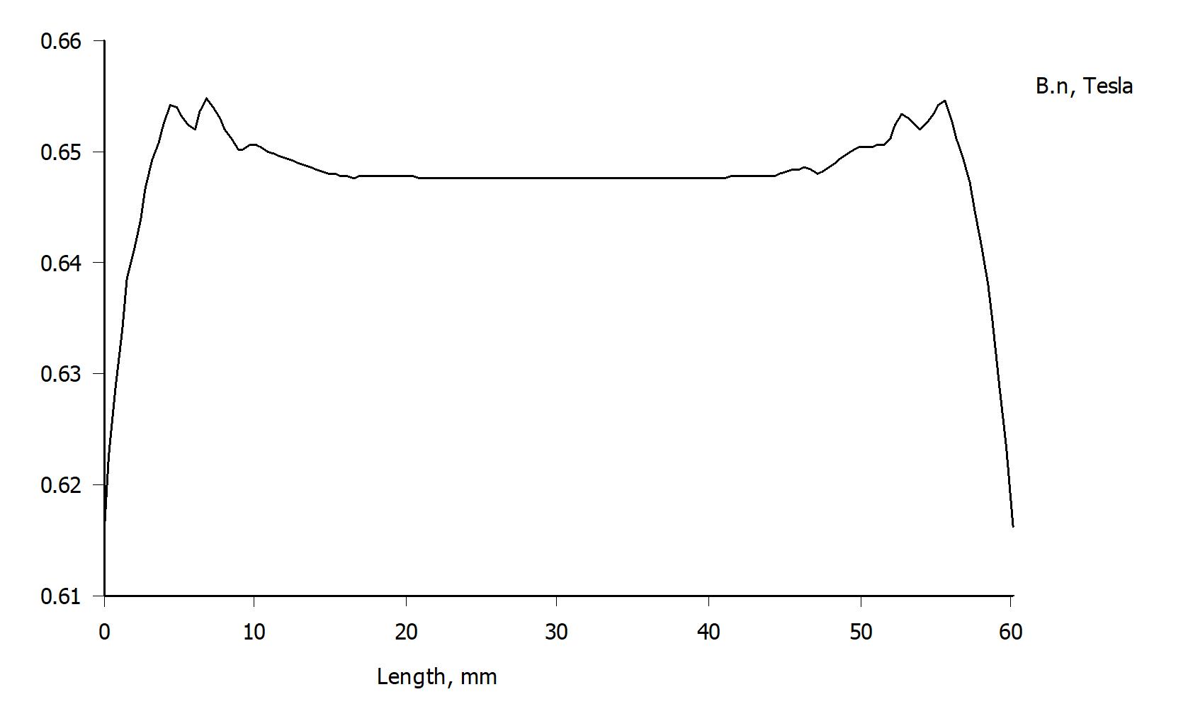
😱.Nice flux in the gap,and very linear
Yes, 30 % increase of the flux density is not bad.
Thank you, Bernt!
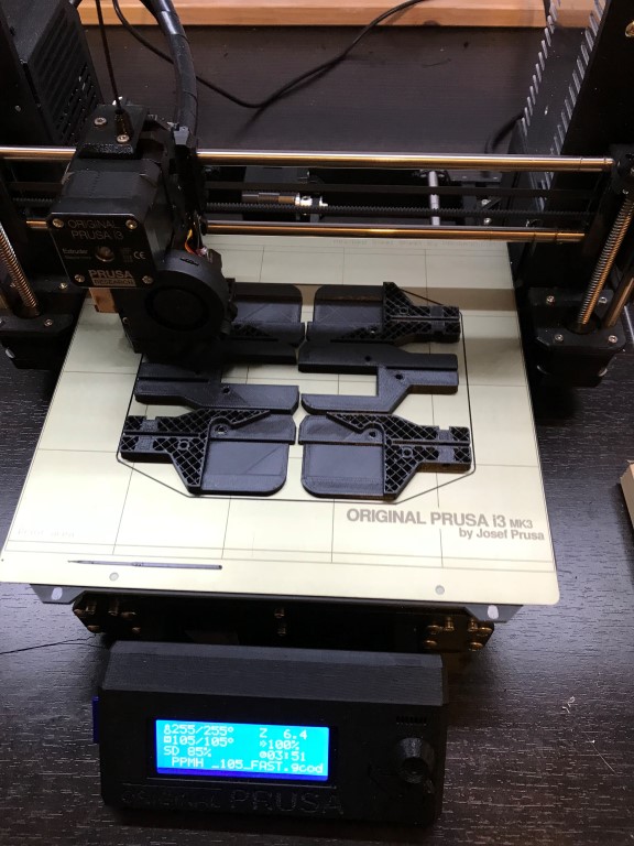
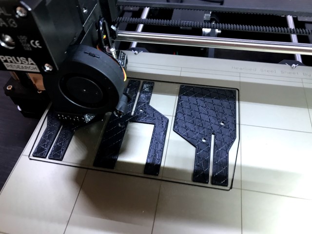
Finally got my 3D-printer, Prusa i3 Mk3, a couple of days before christmas:
It took 1 hour and 53 minutes to print 2 cm of one side of SLAM!.
So the building rate is 0,5 cm an hour.
ABS filament at 0,2 mm height and 20 % fill.
I guess it will take a couple of iterations before I am satisfied with design.
One huge advantage with this building practice is that a smooth front can be made with any diffractional edges.
But this is not the case yet.
An externally hosted image should be here but it was not working when we last tested it.
It took 1 hour and 53 minutes to print 2 cm of one side of SLAM!.
So the building rate is 0,5 cm an hour.
ABS filament at 0,2 mm height and 20 % fill.
I guess it will take a couple of iterations before I am satisfied with design.
One huge advantage with this building practice is that a smooth front can be made with any diffractional edges.
An externally hosted image should be here but it was not working when we last tested it.
But this is not the case yet.
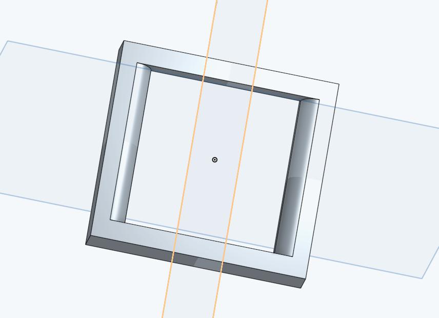
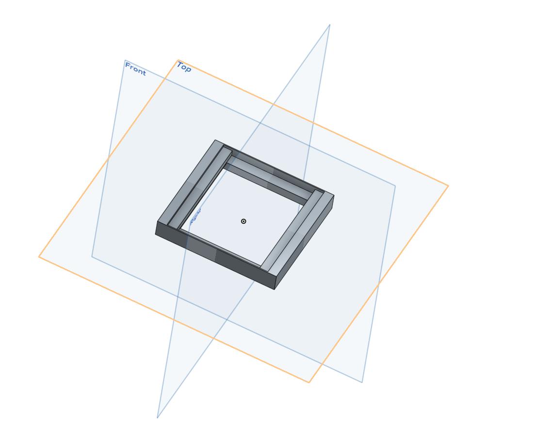
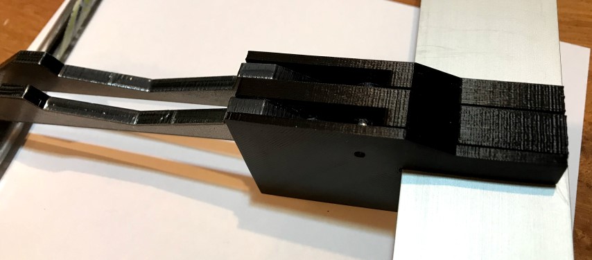
Some iterations later:
Front:
Back, with room for the back pole pieces that will be mounted after the membrane:
As you can see prototype is armed, the magnets will be glued to the side parts in the series specimens.
And the plastics will be black; it was a little easier to evaluate the prototypes using white.
A rim has been added for the membrane holder. Usable gap is now 60 mm.
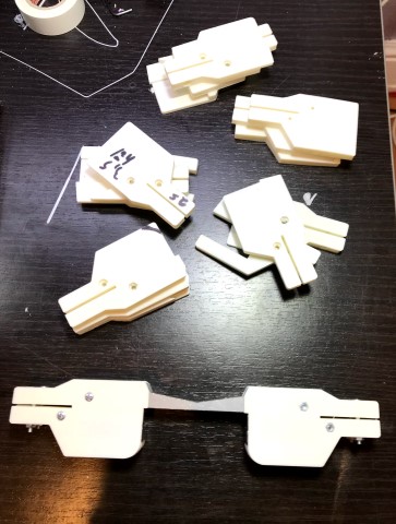
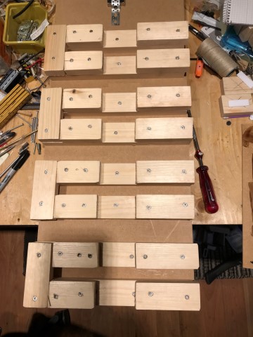
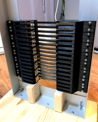
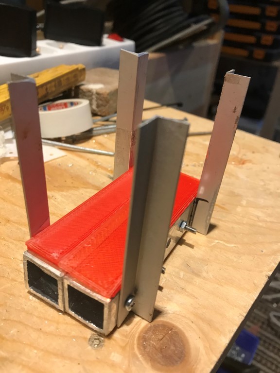
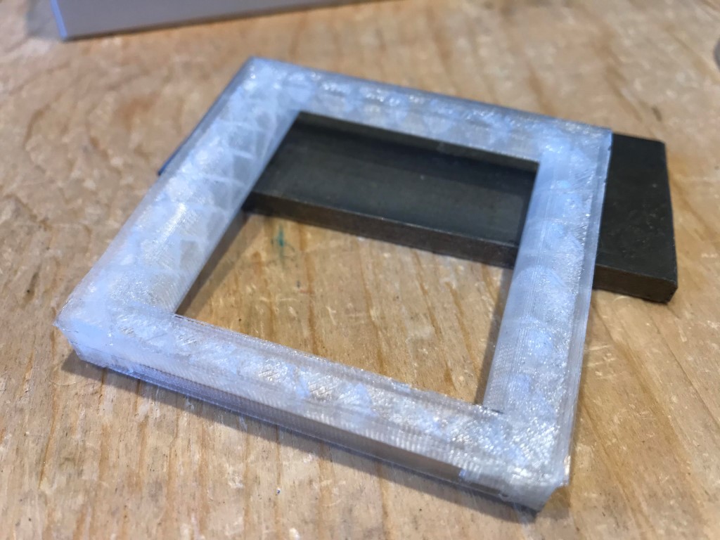
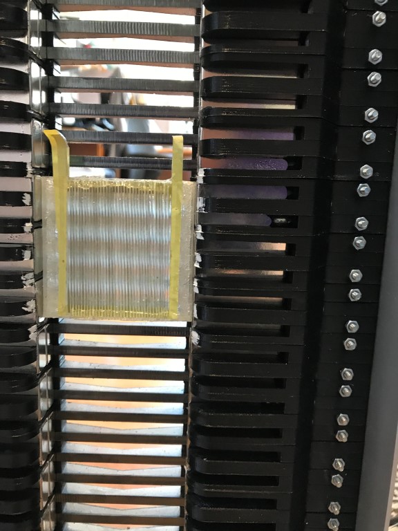
I test mounted the first series segments in the frame:
The segments are be inserted in the cut outs at the top and then pushed down to the already mounted segments.
The segments are be inserted in the cut outs at the top and then pushed down to the already mounted segments.
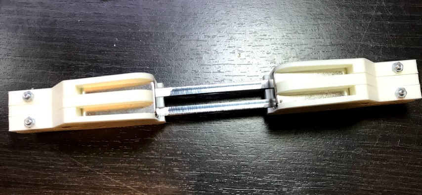
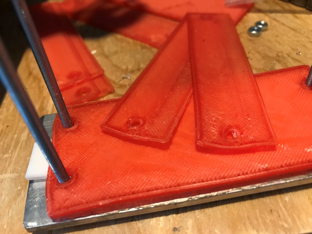
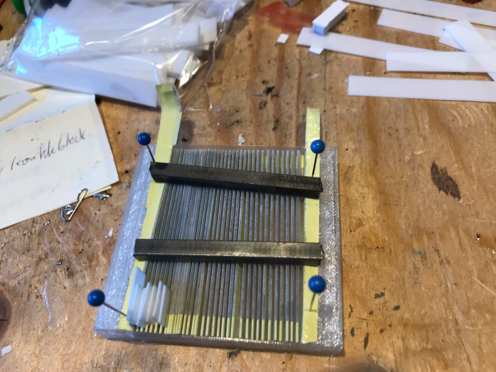
Jig for four segments during hardening:
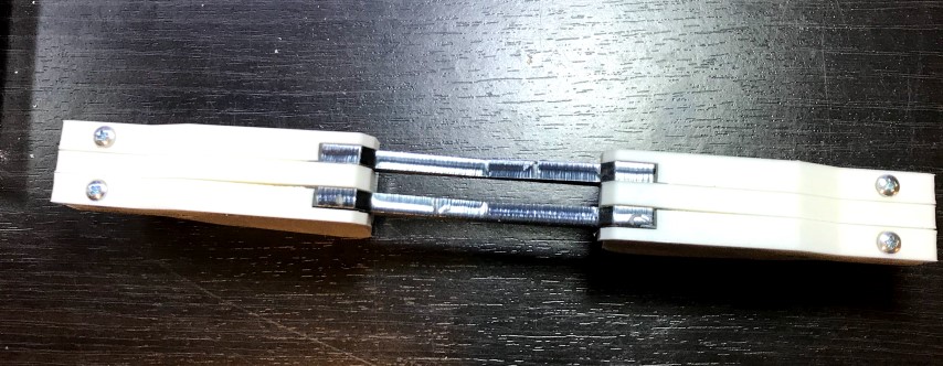
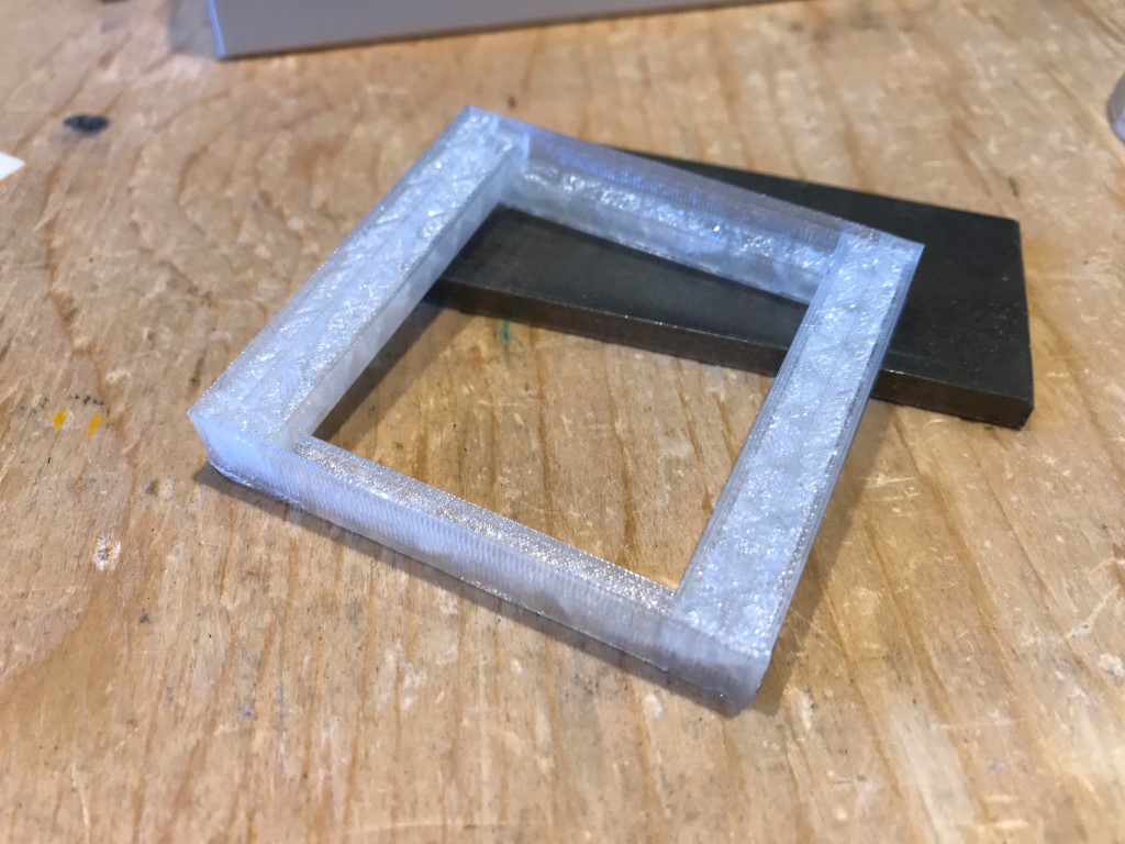
With four segment and some Loctite Power Epoxy:
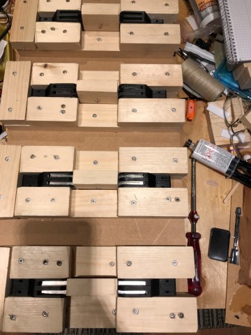
Close up:
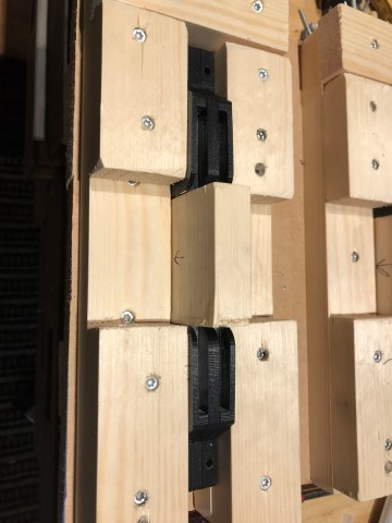
The block in the gap as 66 mm and pushes the magnets during the hardening.
They actually stay there without glue, but vibrations can make them wander and then its - kaboom!
With four segment and some Loctite Power Epoxy:
Close up:
The block in the gap as 66 mm and pushes the magnets during the hardening.
They actually stay there without glue, but vibrations can make them wander and then its - kaboom!
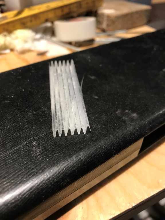
Designed the tweeter membrane:
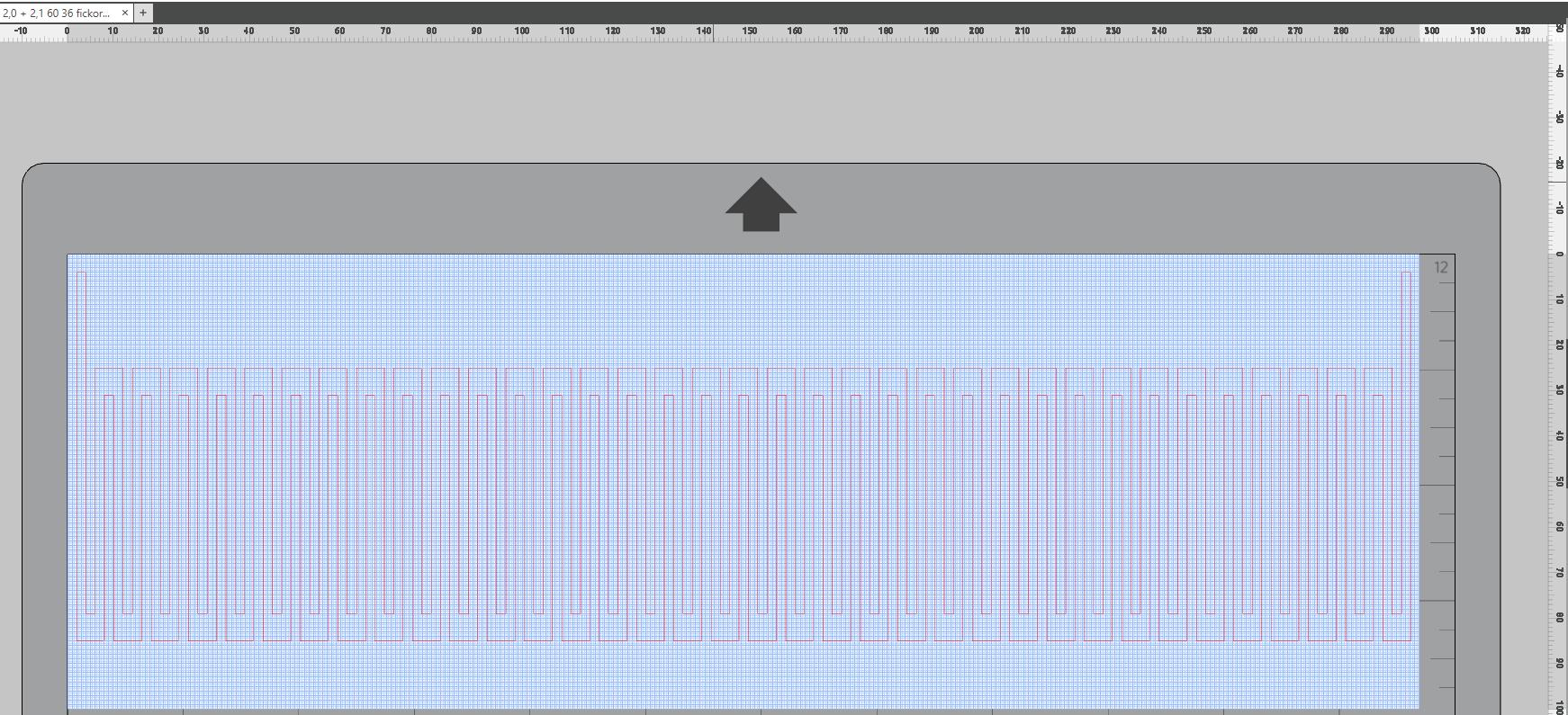
60 mm high and 290 mm wide will with 36 pockets yield a 48x48 mm finished membrane.
The first successful cut:
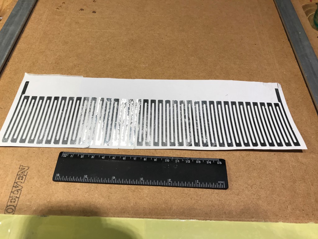
6.0 Ohm, a little bit more than the calculated 4.3 Ohm. But the return feeds, the horisontal parts, were not included in that calculation.
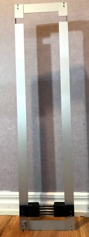
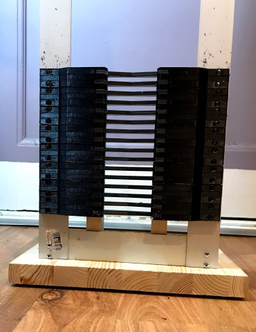
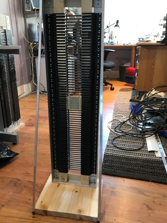
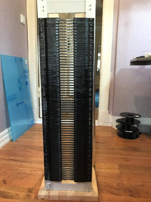
The motors are growing centimeter by centimeter:
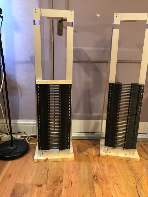
Weight is now a mere 12 kg, 50 cm high.
Only 30 cm to go!
The 3D printer is working 8 hours a day:
Next step is to design a folding tool in nylon.
I have tested nylon and it seems to withstand 170 degrees Celsisus, at least for 20 minutes.
60 mm high and 290 mm wide will with 36 pockets yield a 48x48 mm finished membrane.
The first successful cut:
6.0 Ohm, a little bit more than the calculated 4.3 Ohm. But the return feeds, the horisontal parts, were not included in that calculation.
The motors are growing centimeter by centimeter:
Weight is now a mere 12 kg, 50 cm high.
Only 30 cm to go!
The 3D printer is working 8 hours a day:
Next step is to design a folding tool in nylon.
I have tested nylon and it seems to withstand 170 degrees Celsisus, at least for 20 minutes.
It didn't turn out well with the nylon plates:
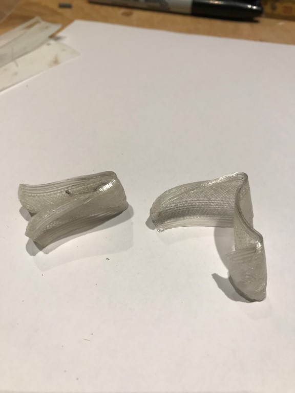
But I found out that the kitchen oven "ovel shoot" when it comes to the temperature. It was actually over 240 degrees.
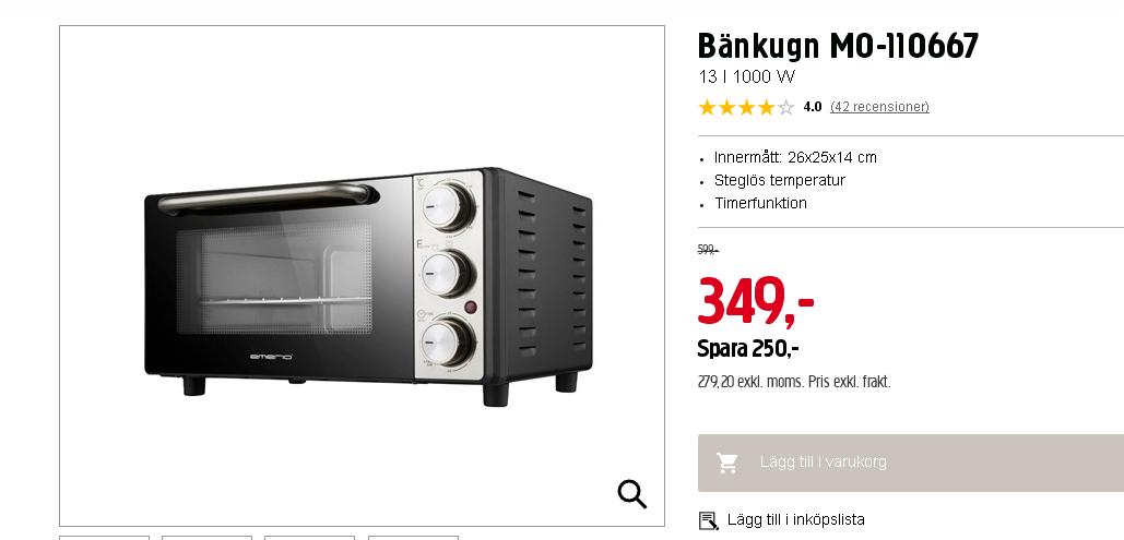
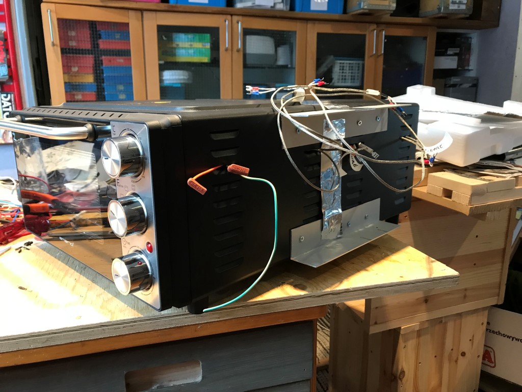
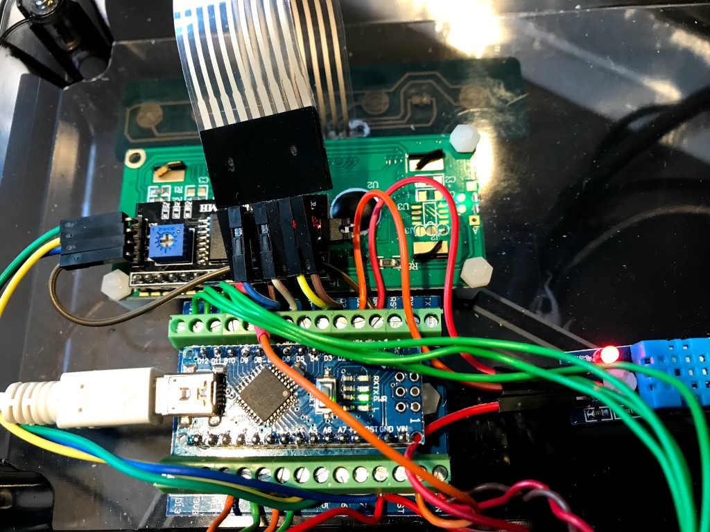
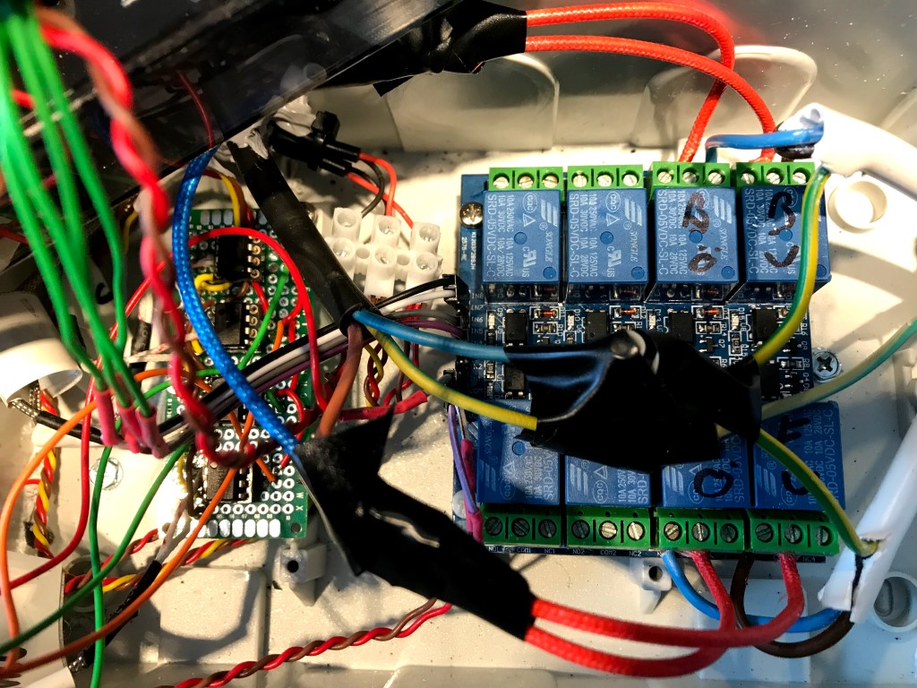
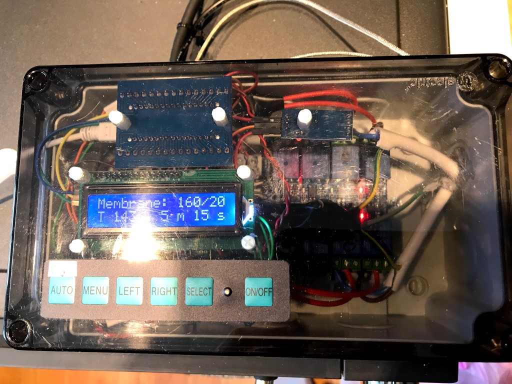
So I decided to build an oven out of two of these and some electronics:
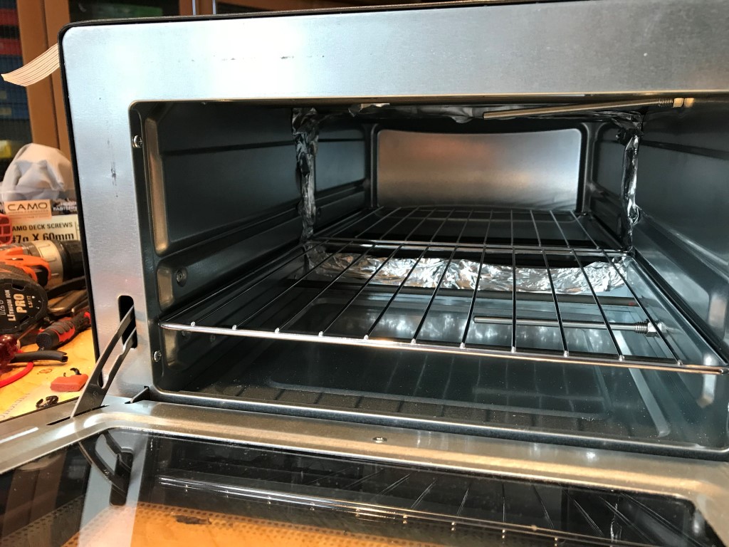
Then I tried poly carbonate at 160 degrees, but that was to hot as well:
Another type of jigg:
and a lower temperature, 140 degrees, did the trick:
But I found out that the kitchen oven "ovel shoot" when it comes to the temperature. It was actually over 240 degrees.
So I decided to build an oven out of two of these and some electronics:
Then I tried poly carbonate at 160 degrees, but that was to hot as well:
Another type of jigg:
and a lower temperature, 140 degrees, did the trick:
To fold the whole membrane in the new jigg went well as did baking it.
But the printer wasn't happy about it when I tried to make prototypes of the membrane holder:
Front:
Back:
As the holder was to be made in a softer material called TPU with a shore of 95A, didn't the extrusion gear manage to feed the extruder.
So I needed to re-build the printer. Luckily, there's a forum for that as well..
Anyway, after a week or so I managed to get a suitable membrane holder:
Front:
Back:
So in with the membrane and prepare for gluing:

Need to rethink your pic posting strategies...?
Everything (certificate, server, firewall) seems fine at my end.
Trouble shooting is ongoing...
Seems to work now? I can now see the pictures on my phone.
Anyway. One tweeter mounted in SLAM!
Back:
Front:
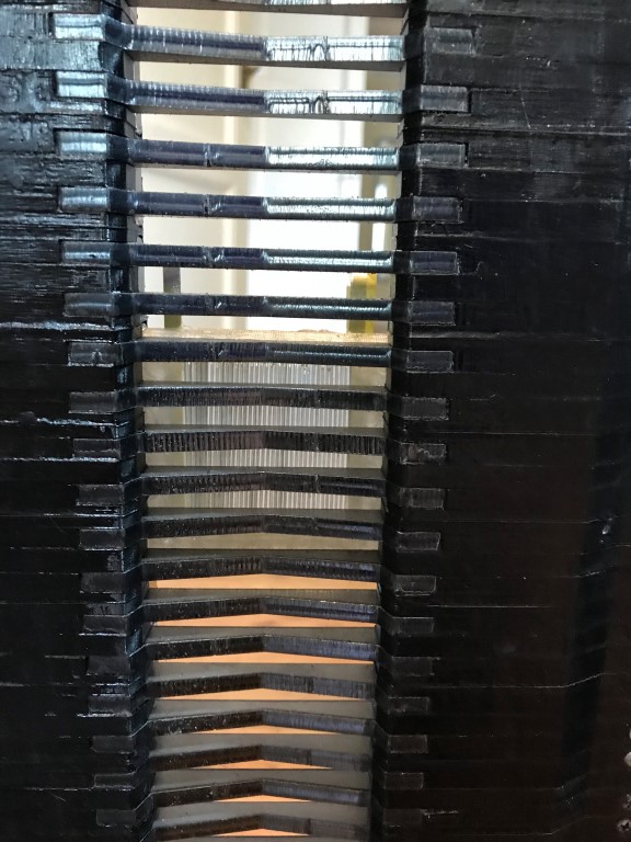
Time to make some measurements...
Anyway. One tweeter mounted in SLAM!
Back:
Front:
Time to make some measurements...
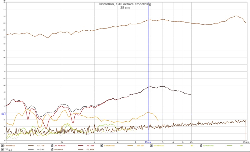
With one watt in and a sweep from 1000 Hz to 20 kHz I got:
At 25 cm:
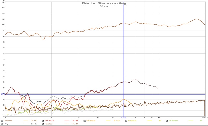
At 50 cm:
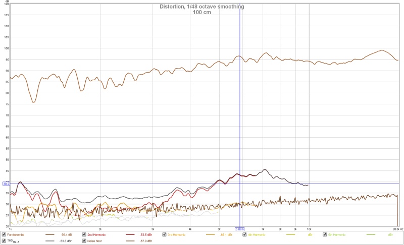
At 100 cm (room starts to influence):
All three:
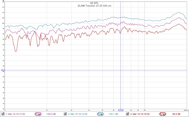
I think it looks good.
Nothing that points to a reconstruction of the membrane.
Next step is to make the terminals better
At 25 cm:
At 50 cm:
At 100 cm (room starts to influence):
All three:
I think it looks good.
Nothing that points to a reconstruction of the membrane.
Next step is to make the terminals better
- Status
- Not open for further replies.