I'm not good at reflex calculations, being a closed box fan, and mainly into crossovers. But I'd like to see the crossover. Maybe something we can do there.Hi. Thanks! The port worked out to 33cm for 53Hz, and is 50mm diameter. Quite long!
I'm not sure what the 85dB sensitivity quote is for, maybe at Fs? I just know the spec I got said that, and also 87dB nominal, which seems to be correct because i balanced the tweeter with a 10 ohm resistor, and it has a sensitivity of 90dB.
Either way, they do go loud. At least, loud enough. For very small speakers, I'd say they're average ito loudness.
You're gonna get some cone breakup form the kevlarish woofer around 8Khz, and maybe the tweeter could get some help.
Yes, thanks, I meant to add a bit about the crossover. It's a 2nd order at 2.5kHz. Ideal would be 4kHz, as the mid/bass driver will go that far, it's well above resonance of the tweeter (1.5kHz), and is above where the tweeter seems to distort. The manufacturer also mentions 4kHz. I don't want to tinker with the crossover, but in an ideal world would make my own. The crossover I got was what was available.
Mate, I'm offering help for free here. 🙂
4kHz crossover for sure with a mylar 1/2" dome and a 5" bass.
So you've used some off-the-shelf simplistic 2.5 kHz crossover. But, let's be honest, you don't know what you are doing. It's a subtle game, best moved forward with detail and honesty.
4kHz crossover for sure with a mylar 1/2" dome and a 5" bass.
So you've used some off-the-shelf simplistic 2.5 kHz crossover. But, let's be honest, you don't know what you are doing. It's a subtle game, best moved forward with detail and honesty.
Mate, I'm offering help for free here. 🙂
4kHz crossover for sure with a mylar 1/2" dome and a 5" bass.
So you've used some off-the-shelf simplistic 2.5 kHz crossover. But, let's be honest, you don't know what you are doing. It's a subtle game, best moved forward with detail and honesty.
Thank you for the help! 🙂
Are you saying 4kHz should be a wise choice? Or not?
I do know what I'm doing, I just don't have much 2-way experience for hifi. I know very well how to change the crossover, but wife-acceptance factor is nowhere at the moment, especially with her being in hospital at the moment (it's been a tough pregnancy).
If you think 4kHz should do much better, I will open those guys up and change them if I find an hour. I usually do my building at 1am-4am, but that's a time that isn't being as available as in the past.
The capacitors are 5uF each. I believe I can keep these and change the inductors to 0.32mH? I don't have time to do much more than that with compensation circuits, etc., but if you have a suggestion, I'll see what I can do with my limited time.
I could possibly do the compensation circuits. If I find the time. For the tweeter I could have an LRC with 15 ohms, 5uF and 0.8mH, and for the woofer, an RC with 7 ohms and 33uF. Then I can keep the 5uF capacitors in the crossovers and change the inductors to 0.3mH. Am I on the right track?
It just seems the resistors would need to be very high wattage resistors?
It just seems the resistors would need to be very high wattage resistors?
Last edited:
This, perhaps?
I can probably get rid of the Zobel network of R5 and C5.
An externally hosted image should be here but it was not working when we last tested it.
I can probably get rid of the Zobel network of R5 and C5.
Couldn't make a lot of sense of that circuit, Mrcloc.
I thought I could have a look at your tweeter modelling with this similar one:
DTW 72 - 8 Ohm
But alas, some technical difficulties with an incomplete driver file.
Downloads
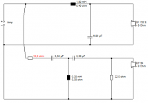
But I had a bash with something not too far away and came up with this circuit, which is a 3.5kHz crossover. I couldn't reuse the 5uF, they were nowhere near what I wanted. This is really quite off-the-shelf for a 5" plus tweeter. I can't say exactly what the red resistor should be. Select by ear. But I think it's about where you want to be.
I thought I could have a look at your tweeter modelling with this similar one:
DTW 72 - 8 Ohm
But alas, some technical difficulties with an incomplete driver file.
Downloads
But I had a bash with something not too far away and came up with this circuit, which is a 3.5kHz crossover. I couldn't reuse the 5uF, they were nowhere near what I wanted. This is really quite off-the-shelf for a 5" plus tweeter. I can't say exactly what the red resistor should be. Select by ear. But I think it's about where you want to be.
Attachments
Couldn't make a lot of sense of that circuit, Mrcloc.
I thought I could have a look at your tweeter modelling with this similar one:
DTW 72 - 8 Ohm
But alas, some technical difficulties with an incomplete driver file.
Downloads
But I had a bash with something not too far away and came up with this circuit, which is a 3.5kHz crossover. I couldn't reuse the 5uF, they were nowhere near what I wanted. This is really quite off-the-shelf for a 5" plus tweeter. I can't say exactly what the red resistor should be. Select by ear. But I think it's about where you want to be.
Fantastic, thank you! I can give this a go, if I get a chance. Should be an easy one to build.
This is the tweeter:
SC5
In my circuit, C7, L7, L5 and C3 form the crossover, 2nd order Chebychev, Q=1. R5 and C5 are on the board already, but I can use the 5 ohm for R7 rather. The LRC across the tweeter and the RC across the woofer are compensation circuits which provide a much better impedance curve. The values are calculated from circuits modeled on the specific tweeter and woofer. I modified the resistors R7 and R8 so that I can use some 10 ohm 10W resistors I have. The response changes are minimal.
I like your schematic, because you seem to have a bit of experience with this, and it's quite simple and doable. The red resistor will be 10 ohms - I assume this balances the tweeter's sensitivity, and I have matched this already.
You are kidding me! You have the visaton tweeter? 😀
SC 5 - 8 Ohm
I'll get onto the SC5 now. It's a bit of a nightmare IIRC. 😎
SC 5 - 8 Ohm
I'll get onto the SC5 now. It's a bit of a nightmare IIRC. 😎
You are kidding me! You have the visaton tweeter? 😀
SC 5 - 8 Ohm
I'll get onto the SC5 now. It's a bit of a nightmare IIRC. 😎
😀
Thanks! I have the models of the speakers in a sim, so I can easily add your schematic to it. 🙂
It's weird, I was just going to suggest the below circuit when you told me the exact tweeter. Because it has nice impedance, and is actually an old KEF filter that I use a lot.
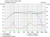
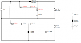
Anyway, I think this is about as good as it gets. The dip at 5kHz is a phase problem that shouldn't sound too bad. Ignore the detailed W130S response. It's just a guide really. Interestingly, the TW 70 - 8 Ohm will slot in without a murmur. Very different sound, of course.
I think we are on safe ground here. You can use your 5uF for the 4.7uF, won't make much difference. FWIW, that LCR on the right is a tweeter Fs 2kHz notch that goes where the 0.2mH coil is, but it didn't really help.
Attachments

Last edited:
This is great, thank you! I will do my best to squeeze out some time to make this. I'm keen to hear a difference, which I'm sure there will be. Thanks for taking the trouble!
I'm curious, do you think it's a good idea to add a damping resistor across the woofer? perhaps a 50-70 ohm?
I'm curious, do you think it's a good idea to add a damping resistor across the woofer? perhaps a 50-70 ohm?
I can't see a lot of point in that. Just wastes power really.
Tricks of the trade worth trying are tank notches, here acting around 5-10kHz to take down bass cone breakup about 6dB, and a resistor in the bass shunt to align phase.
TBH, you have to stop somewhere or it just gets unmanageable and hard to build. But the 33R and 0.22uF is something I use in this sort of speaker.
Attachments
I can't see a lot of point in that. Just wastes power really.
Tricks of the trade worth trying are tank notches, here acting around 5-10kHz to take down bass cone breakup about 6dB, and a resistor in the bass shunt to align phase.
TBH, you have to stop somewhere or it just gets unmanageable and hard to build. But the 33R and 0.22uF is something I use in this sort of speaker.
That's a nice notch there. If I build the crossover, I may as well add it. I like what it does to the response.
That TW 70 - 8 looks nice, but I don't have any choice, basically. My stuff is ordered from far, and on a bit of a budget. I didn't have much to choose from in the first place. The tweeter I got was a compromise of sensitivity, response, availability and cost.
Do you think a former is all that necessary for the inductors? Or can I simply wind them and epoxy or hot glue them tight?
Do you think a former is all that necessary for the inductors? Or can I simply wind them and epoxy or hot glue them tight?
Discard that. I see you need many windings, so a former makes it much easier.
Speaker box design
Here is my enclosure design:
All dimensions are inner dimensions. The PVC pipe is the 50mm, whatever it's diameter is (51, 52, 50?).
There is about 7mm soft cloth stuck on the wood behind the vertical part of the port to provide a cushion for it. There is also some stuffing in the box.
Here is my enclosure design:
All dimensions are inner dimensions. The PVC pipe is the 50mm, whatever it's diameter is (51, 52, 50?).
An externally hosted image should be here but it was not working when we last tested it.
There is about 7mm soft cloth stuck on the wood behind the vertical part of the port to provide a cushion for it. There is also some stuffing in the box.
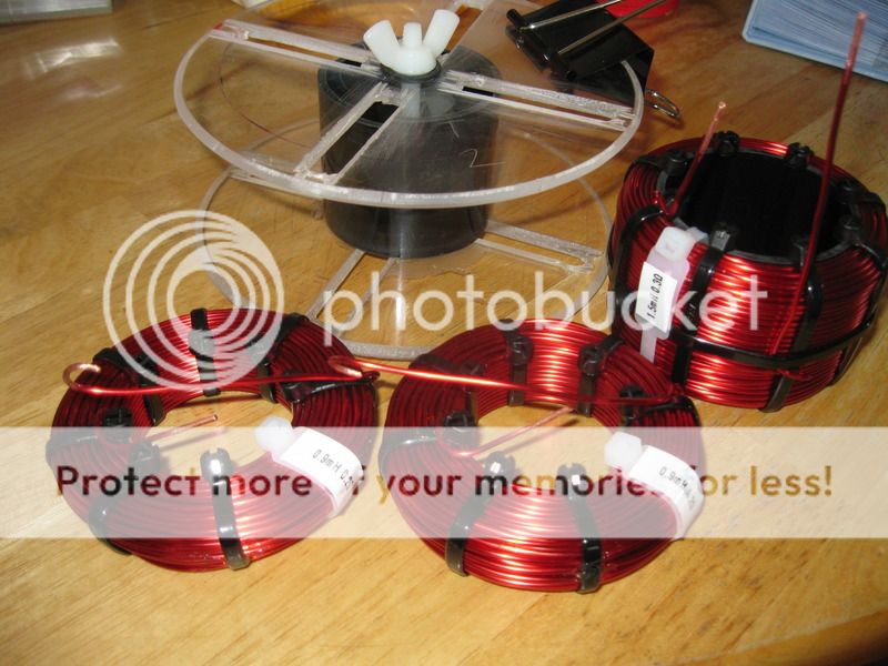
wolf_teeth (I expect he has a real name...LOL) winds his own coils using enamelled (insulated) copper wire. And he's a pretty sound bloke. You have to scrape the enamel off at the ends when soldering, of course. And modern solder needs 40W guns at least. Always tin it with solder the first time it warms up, otherwise it oxidises to black the modern tip and it is unfixable. Gone are the days of sanding down a copper tip for poisonous leaded solder.
http://www.diyaudio.com/forums/multi-way/291421-crossover-capacitors-4.html#post4726640
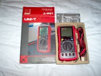
You need a good expensive meter with an inductance scale to get it right. Perhaps borrow one from an electrician or alarm engineer. Ferrite cores increase inductance about fourfold, with all the potential non-linearities at large signal.
Happily in the UK it's easy enough to buy tag strip, zip ties and blocks, and coils ready made. One of my own crossovers below. I tend to use 10W or 7W or 3W ceramic wirewounds. Oh, an alarm engineer told me when crimping thin wire to spade terminals for speakers, double the wire back for thickness before crimping. Good tip.
http://www.diyaudio.com/forums/multi-way/291421-crossover-capacitors-4.html#post4726640
You need a good expensive meter with an inductance scale to get it right. Perhaps borrow one from an electrician or alarm engineer. Ferrite cores increase inductance about fourfold, with all the potential non-linearities at large signal.
Happily in the UK it's easy enough to buy tag strip, zip ties and blocks, and coils ready made. One of my own crossovers below. I tend to use 10W or 7W or 3W ceramic wirewounds. Oh, an alarm engineer told me when crimping thin wire to spade terminals for speakers, double the wire back for thickness before crimping. Good tip.
Attachments
Last edited:
Hi system7. Thank you for the work you put into this, even though there's a big chance I can't even do it! At least I've learned a lot, and I definitely take a lot away from this. I was going to build the crossovers, but unfortunately the cost of the inductors was just going to be too high, and out of reach of my budget by quite a bit. And I just don't have time. I've tried, but with a baby due to arrive, things are far too busy.
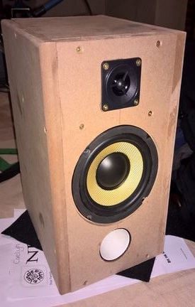
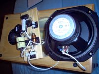
Anyway, I did finish off one speaker. The finish isn't fantastic, but it doesn't look too bad. At least it looks complete. I'll finish the other one soon and hopefully my friend enjoys these for years. Oh, and in real life, those lighter bits are not really that light.
Anyway, I did finish off one speaker. The finish isn't fantastic, but it doesn't look too bad. At least it looks complete. I'll finish the other one soon and hopefully my friend enjoys these for years. Oh, and in real life, those lighter bits are not really that light.
An externally hosted image should be here but it was not working when we last tested it.
- Status
- Not open for further replies.
- Home
- Loudspeakers
- Multi-Way
- Skytronic Drivers